📌 Key Takeaways
Standardized Audio Precision testing removes guesswork from amplifier quality control by replacing subjective operator judgment with automatic pass/fail data tied to each unit’s serial number.
- Operators Can’t Catch What Instruments Can: Three technicians testing the same amplifier often give three different verdicts—AP testing gives one clear answer based on fixed limits, not human judgment.
- Class D Amps Hide Problems Well: Switching amplifier designs can mask distortion that only shows up under heat and load—issues a quick listening test won’t reveal but warranty claims will.
- Golden Samples Prove Design, Not Production: A hand-built prototype passing tests doesn’t guarantee factory-built units will perform the same without objective measurement gates along the way.
- Ask for Evidence, Not Promises: Request sample test reports with marked thresholds, calibration certificates, and serial-number-linked data retention before trusting an OEM partner’s quality claims.
- Test Data Turns Arguments into Answers: When a unit fails in the field, pulling its FQC record in minutes replaces days of guesswork with specific measurements to trace the problem.
Objective test data turns “quality” from a marketing promise into an auditable contract.
Sourcing Directors and Acoustics Managers evaluating OEM amplifier partners will gain a practical audit framework here, preparing them for the detailed implementation checklist that follows.
~ ~ ~ ~ ~ ~ ~ ~ ~ ~ ~ ~ ~ ~ ~ ~ ~ ~ ~ ~ ~ ~ ~ ~ ~ ~ ~ ~ ~ ~ ~ ~ ~ ~ ~ ~ ~ ~ ~ ~ ~ ~ ~ ~ ~ ~ ~ ~ ~ ~ ~ ~
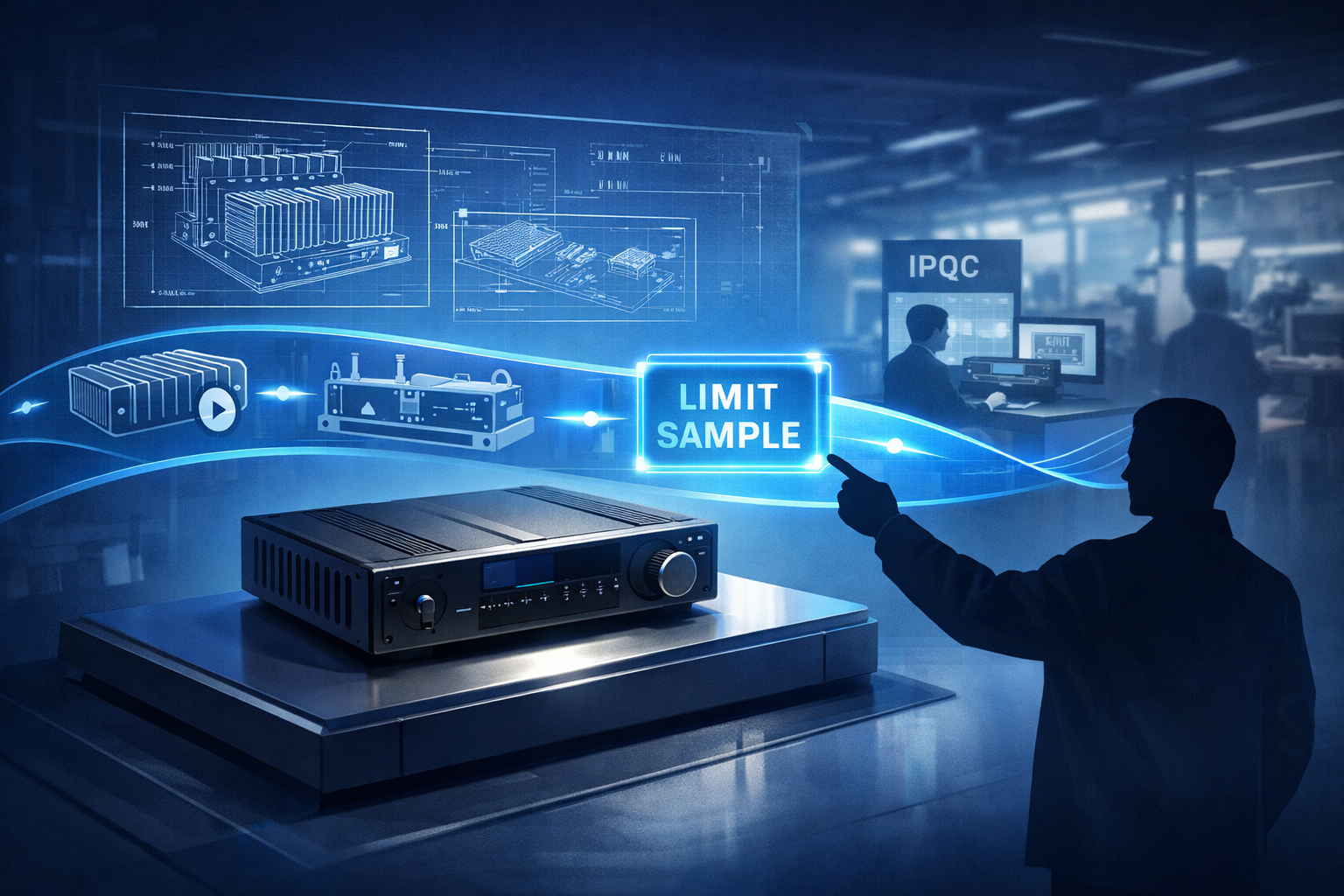
It’s 9:00 AM on a Tuesday. The Sourcing Director is staring at a batch of failed thermal tests from an EVT sample, realizing the Q4 product launch is now dangerously behind schedule. The spreadsheet shows three different operators logged three different verdicts on the same unit last week. Nobody can pinpoint what changed—or whether anything changed at all.
This scenario plays out across OEM programs whenever final quality control relies on subjective methods. For high-wattage Class D amplifiers, operator judgment and occasional listening tests simply cannot catch the subtle distortion, noise floor drift, or thermal-related anomalies that multiply at production scale. The fix is not more inspectors. The fix is standardized, instrument-based verification that removes argument from the equation.
AP-integrated Final Quality Control (FQC) uses a standardized Audio Precision measurement sequence and fixed acceptance limits to verify each finished amplifier’s key performance and safety-adjacent parameters—distortion, noise, output behavior—before shipment. It transforms QC from a judgment call into an auditable dataset tied to the unit’s serial number.
Why Subjective Final QC Breaks Down on High-Power Class D Amplifiers
Subjective FQC typically means ad-hoc meter checks, occasional listening tests, and operator discretion on borderline units. Two problems make this approach fail at scale.
Operator variance introduces inconsistency. The same amplifier tested by three technicians can yield three different verdicts depending on ambient noise, fatigue, or interpretation of vague criteria. When your production run hits thousands of units, that variance becomes a systemic leak that erodes yield data integrity.
Class D power stages behave differently than traditional linear amplifiers. Their switching topologies can mask subtle distortion artifacts that only manifest under specific load and thermal conditions. A technician listening briefly at moderate volume will not catch a noise floor issue that appears at rated power after thermal stress. These are precisely the defects that become field failures—and warranty costs—six months later.
A common misconception accelerates this problem: assuming that a “golden sample” passing DVT guarantees mass production will behave identically. The golden unit proves the design can meet spec. It does not prove every line-built unit will meet spec unless the process is governed by objective gates and measurement correlation. Small changes in assembly, component tolerances, and thermal behavior stack differently across a production run than they do in hand-built prototypes.
The downstream impact hits brand equity directly. Inconsistent FQC means inconsistent shipped quality, which means unpredictable field failure rates and warranty exposure. For pro audio distributors, the failure mode is often not “dead on arrival”—it is “degrades in deployment,” which is harder to diagnose and more expensive to resolve. For Sourcing Directors tracking Total Cost of Ownership, that variance is unacceptable. For Acoustics Managers defending their spec sheet in front of channel partners, it is a credibility risk.
What “AP-Integrated FQC” Means in Practice
AP integration is not simply buying an analyzer. It is integrating repeatable measurement methodology into the end-of-line workflow so that shipped units are measurably consistent with DVT-defined expectations.
An AP-integrated FQC station consists of an Audio Precision analyzer, a repeatable test fixture, a scripted measurement sequence, a limit table defining pass/fail thresholds, and a data capture system that logs results per serial number.
“Standardized” means every unit sees the same stimulus, the same measurement chain, the same acceptance thresholds, and the same revision-controlled test script. The analyzer executes the sequence automatically—often in under two minutes—and returns a binary pass/fail verdict with full measurement data retained.
What AP-based FQC does not do is replace design validation testing (DVT) or safety certification. FQC verifies that a finished, assembled unit performs within the spec envelope your DVT process already validated. It confirms production consistency, not design adequacy.
This distinction matters when auditing an OEM partner. Ask whether their AP setup is configured for production-mode testing with defined limits, not exploratory R&D sweeps. Production mode prioritizes speed and repeatability; R&D mode prioritizes diagnostic depth. Both use the same hardware, but the operational discipline differs entirely.
The Minimum Measurement Set to Standardize
A pragmatic FQC sequence for Class D pro audio amplifiers should cover these core parameters:
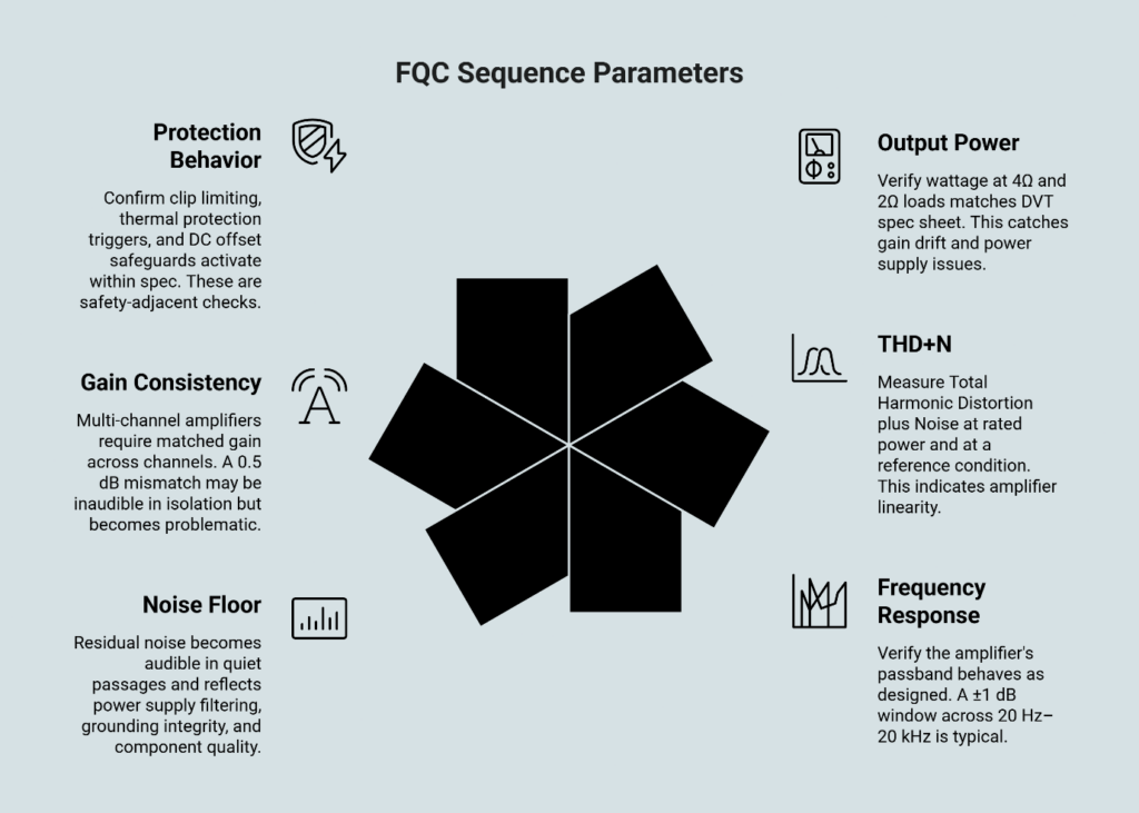
Output power verification at defined loads. Confirm rated wattage at 4Ω and 2Ω loads matches the DVT spec sheet within tolerance. This catches gain drift and power supply issues.
THD+N at rated power and at a reference condition. Total Harmonic Distortion plus Noise is the primary indicator of amplifier linearity. Measure at rated power (where thermal stress is highest) and at a mid-power reference point (where component variation shows). Methodologies align with IEC 60268-3 amplifier measurement standards, with AES17-2020 providing additional context where digital-audio measurement definitions apply.
Frequency response or band-limited flatness. Verify the amplifier’s passband behaves as designed. A ±1 dB window across 20 Hz–20 kHz is typical for pro audio applications.
Noise floor and SNR. Residual noise—including idle noise, hum components, and broadband noise—becomes audible in quiet passages and reflects power supply filtering, grounding integrity, and component quality.
Gain consistency and channel balance. Multi-channel amplifiers require matched gain across channels. A 0.5 dB mismatch may be inaudible in isolation but becomes problematic in bridged configurations or multi-amp systems.
Protection behavior verification. Confirm clip limiting, thermal protection triggers, and DC offset safeguards activate within spec. These are safety-adjacent checks that prevent field failures and liability exposure.
The specific numeric thresholds depend on your program spec sheet and SKU requirements. The point is to define limits before production starts—not to invent them when failures appear.
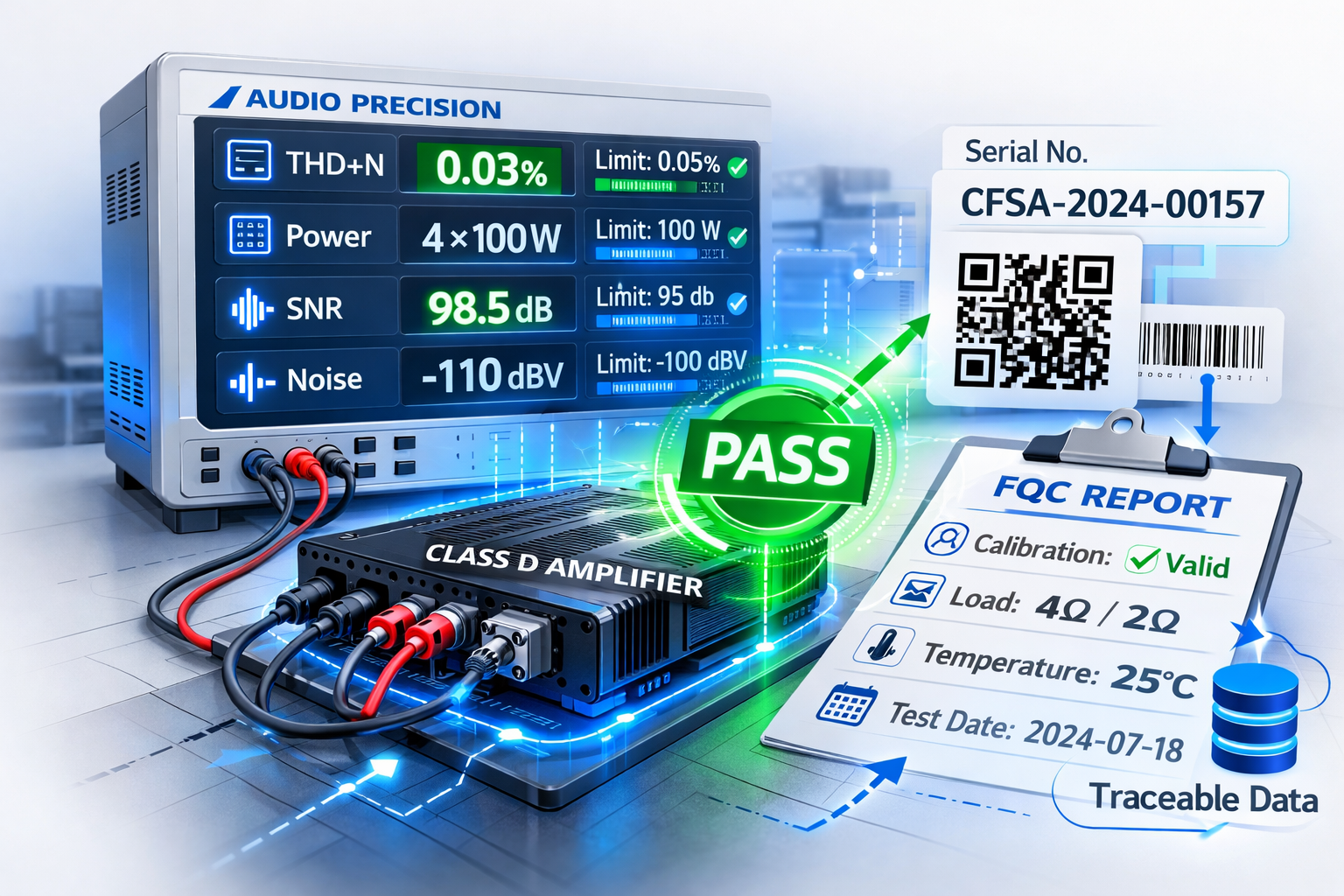
What a Standardized FQC Record Looks Like
A standardized, AP-generated end-of-line record transforms quality from an argument into a dataset. The following illustrative example shows what this looks like in practice—thresholds are representative formats, not claims about any single product’s required limits.
Unit ID: SN-QA-240228-0187 (QR bound) Station: AP-FQC-03 (cal status: in date) Load: 4 Ω resistive fixture (verified) Ambient: 25°C (logged)
Noise & Hum (Inputs shorted)
- A-weighted noise (dBV): Measured −88.4 | Limit ≤ −85.0 | PASS
- 50/60 Hz hum component (dBV): Measured −78.0 | Limit ≤ −75.0 | PASS
Frequency Response (1 W equivalent)
- 20 Hz deviation (dB): Measured −0.35 | Limit ≥ −0.50 | PASS
- 20 kHz deviation (dB): Measured −0.20 | Limit ≥ −0.50 | PASS
THD+N vs. Output (1 kHz)
- THD+N @ 1 W (%): Measured 0.020 | Limit ≤ 0.050 | PASS
- THD+N @ 10 W (%): Measured 0.045 | Limit ≤ 0.080 | PASS
- THD+N @ target power (%): Measured 0.090 | Limit ≤ 0.120 | PASS
Channel Consistency
- Gain delta L/R (dB): Measured 0.15 | Limit ≤ 0.30 | PASS
- Noise delta L/R (dB): Measured 0.8 | Limit ≤ 1.5 | PASS
Result: PASS — Released to packout Data binding: Stored to lot record; accessible by SN lookup
This kind of readout enables fast containment when failures cluster by lot, station, or upstream component variation. When a field failure occurs, you pull that unit’s FQC record in minutes—not days—and the objective parameters instantly replace subjective guesswork.
How to Integrate AP Testing into the End-of-Line Workflow Without Slowing Throughput
Three operational factors determine whether AP-based FQC helps or hinders production flow.
Fixture design and repeatable connections. The test fixture must enforce consistent cable routing, load connections, and signal paths every time. Operator-proof connectors—keyed, color-coded, and physically constrained—eliminate setup variance. A well-designed fixture lets any trained technician run the sequence identically.
Calibration discipline and version control. The AP analyzer itself requires periodic calibration traceable to national standards. Beyond hardware calibration, the test sequence files and limit tables need revision control. When firmware changes or a BOM substitution occurs, the test program must update in lockstep—and the change must be documented via ECO/ECR protocols.
Failure handling and root-cause feedback. When a unit fails, the system should auto-bin it for retest or quarantine. The measurement data from failures feeds root-cause analysis, enabling process corrections before yield collapse. Facilities using ISO9001-2015 certified quality systems typically integrate this failure data into their In-Process Quality Control (IPQC) feedback loops.
In a disciplined quality-gate stack, AP-driven checks are most effective when positioned as a late-stage verification. A typical high-level flow sequences incoming checks for critical components (IQC), then in-process checks at defined operations (IPQC), followed by final function test for basic operation and protections, then AP-based acoustic and electrical performance verification (FQC), and finally serialization, labeling, and packout. That placement ensures failures discovered by acoustic and electrical metrics are not confused with earlier assembly or connectivity errors and can be routed into containment and corrective action cleanly.
At China Future Sound, the amplifier production workflow sequences AP testing after aging and function verification—positioned as the final technical gate before assembly and packaging. Test data binds to barcodes and QR codes, ensuring traceability from measurement results back to component lots and production dates.
OEM Audit Checklist: What to Ask for Before You Trust the Data
When evaluating an OEM partner’s AP-integrated FQC capability, request evidence—not promises. The following checklist distinguishes rigorous operations from marketing claims:
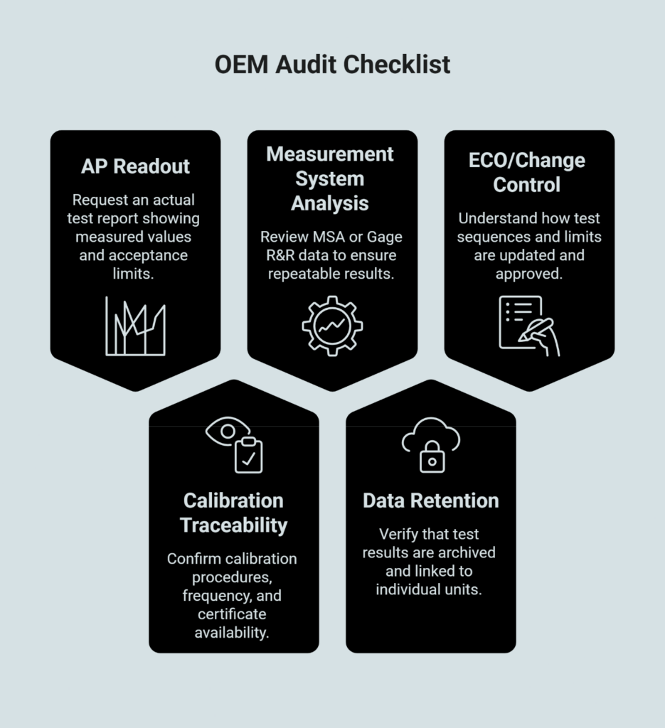
Sample AP readout with pass/fail thresholds marked. Ask for an actual test report showing the measured values alongside the acceptance limits. If they can only show raw plots without defined thresholds, the “standardization” claim is hollow.
Calibration traceability and ownership. Who performs calibration? How often? Is there a certificate on file? Calibration drift in the analyzer itself invalidates every measurement downstream.
Measurement system analysis (MSA) or Gage R&R data. This demonstrates that the test setup produces repeatable results across operators, fixtures, and time. Without MSA evidence, you cannot trust the measurement system’s discrimination capability.
Data retention and serial-number traceability. Confirm that test results are archived and linked to individual units. When a field failure occurs, you need the ability to pull that unit’s FQC record within minutes—not days.
ECO/change control for test sequences and limits. When the product or process changes, how are the test program and limit tables updated? Who approves changes? Undisciplined version control is a leading cause of quality drift after the first production run.
Where certification is presented, third-party verification tools such as IAF CertSearch can validate accredited certificates. This audit mindset applies whether you are qualifying a new OEM partner or re-evaluating an existing one. The questions reveal operational maturity, not just equipment ownership.
Where DFM Intersects with Quality Gates
Design for Manufacturability determines how sensitive the product is to normal process variation. A design that is fragile under tolerance stack-up forces FQC to become an expensive sorting function. A design that anticipates real-world variability allows FQC to be a confirmation gate instead of a triage center.
DFM reduces variance; gates detect and contain what remains. This is why quality gates and DFM should be viewed as coupled systems rather than separate disciplines. For a broader process framing of taking designs to shipped products, see OEM/ODM manufacturing process: design to shipped product.
Turn “Quality” from a Promise into an Auditable Contract
The value of AP in FQC extends beyond marginally tighter specs. The real payoff is eliminating argument. When the test sequence, limits, and calibration discipline are defined and shared, everyone—OEM, Acoustics Manager, Sourcing Director—operates from the same dataset. Disputes about “good enough” disappear. Failure analysis is immediately anchored by empirical metrics.
For program owners managing NPI risk and Total Cost of Ownership, standardized FQC reduces the anxiety of scaling production. You gain confidence that the amplifier shipping in month six matches the amplifier you approved in month one. That confidence accelerates vendor decisions, protects brand equity, and converts “quality” from a subjective promise into an auditable contract.
For teams trying to reduce launch risk and stabilize shipped performance, the most productive next step is an audit-style review of acceptance criteria: what is tested, how limits are set, how data is logged, and how failures are contained. For an offline qualification conversation, use the Contact page.
Frequently Asked Questions
What is Audio Precision testing in amplifier final QC?
Audio Precision testing uses standardized measurement sequences and fixed acceptance limits to verify each amplifier’s distortion, noise, power output, and protection behavior before shipment—replacing subjective operator judgment with auditable pass/fail data.
Which measurements should be mandatory in end-of-line testing for Class D amps?
At minimum: output power at rated loads, THD+N at rated and reference power, frequency response, noise floor/SNR, gain consistency, and protection behavior verification.
How do you set pass/fail limits without slowing production?
Define limits during DVT based on spec sheet tolerances and golden unit performance. The AP sequence then executes automatically, typically in under two minutes per unit.
What evidence should an OEM provide to prove their AP test is standardized?
Request a sample readout with thresholds marked, calibration certificates, MSA/Gage R&R data, serial-number-linked data retention policy, and ECO documentation for test program changes.
What’s the difference between DVT validation testing and FQC testing?
DVT validates that the design meets performance and safety requirements. FQC verifies that each production unit conforms to the validated design—it confirms consistency, not adequacy.
Disclaimer: This content is for informational purposes and reflects general industry practices. Specific measurement parameters, acceptance limits, and test procedures should be defined per program requirements and validated through your own engineering and quality teams.