📌 Key Takeaways
A spec sheet tells a factory what your amplifier should do—a DFM handoff package tells them exactly how to build and test it at scale.
- Pair Every Spec with a Test Method: Requirements without clear test conditions and pass/fail thresholds force factories to guess—causing false failures and schedule delays.
- Flag What Can’t Be Swapped: Mark critical components as “no substitute” in your BOM, or the factory may swap parts that cause performance drift between units.
- Define Thermal Conditions, Not Just Limits: A max temperature spec without airflow assumptions, ambient conditions, and measurement points creates thermal shutdowns during pilot builds.
- Control Firmware Like You Control Hardware: Version-controlled build files and clear rules about what the factory can adjust prevent mixed builds and tuning drift across production lots.
- Send the Package Early: Share your complete handoff documents 48–72 hours before the kickoff meeting so the factory can prepare real questions instead of guessing in real-time.
A complete handoff package eliminates factory guesswork—and the late ECOs that follow.
Brand engineers and product managers launching amplifier programs will find a clear handoff structure here, preparing them for smoother DFM reviews and faster production ramp.
~ ~ ~ ~ ~ ~ ~ ~ ~ ~ ~ ~ ~ ~ ~ ~ ~ ~ ~ ~ ~ ~ ~ ~ ~ ~ ~ ~ ~ ~ ~ ~ ~ ~ ~ ~ ~ ~ ~ ~ ~ ~ ~ ~ ~ ~ ~ ~ ~ ~ ~ ~ ~
The EVT sample passed every lab test. Frequency response, THD, thermal limits—all within spec. Then the first pilot build arrives, and half the units fail thermal shutdown under load. The spec sheet listed a maximum operating temperature, but never defined the ambient conditions, airflow assumptions, or measurement points the factory should use. Now an ECO scramble begins, and the Q4 launch window is slipping.
This scenario plays out more often than it should. The gap between what your spec sheet describes and what a factory can actually build and verify at scale is where programs lose weeks, budgets, and sometimes entire market windows.
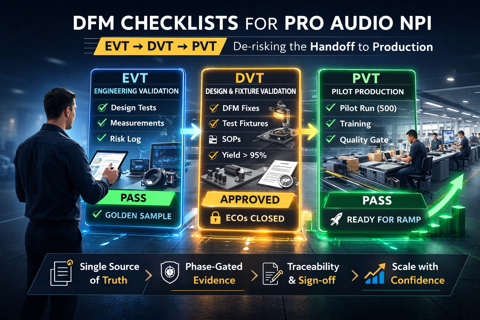
DFM integration is the translation of performance intent into build and test definitions a factory can execute repeatably. It starts not after prototypes, but at the handoff—when your engineering team transfers ownership to the production floor. Think of your specifications as a production contract: measurable requirements, aligned test methods, and unambiguous mechanical and electrical definitions that make the program inspectable, assemblable, and change-controlled before tooling and line validation.
The path from handoff to standard operating procedure follows a predictable sequence: spec package, DFM review, ECO loop, EVT/DVT/PVT validation, then SOP release. If that initial handoff package contains only marketing-grade specifications, you force the factory to interpret, improvise, and iterate. The result is predictable: tolerance stackups that don’t work, test conditions that create false failures, and thermal strategies that exist on paper but not in sheet metal.
This guide provides the exact structure for a DFM-ready handoff package, so your OEM partner can begin their review without guesswork.
Why Your Amp Spec Sheet Isn’t Enough for DFM
A spec sheet describes intent. A DFM package describes execution.
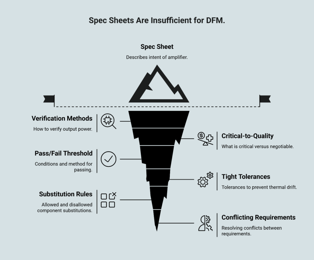
Your product requirements document might state “output power: 500W RMS into 4Ω.” That tells a factory what the amplifier should achieve. It does not tell them how to verify it, under what conditions, with what measurement equipment, or what variance is acceptable before a unit fails inspection.
A typical amplifier spec sheet rarely answers the questions a factory must resolve to build consistent units at scale:
- What is critical-to-quality versus negotiable?
- What is the pass/fail threshold, under what conditions, using what method?
- Which tolerances must be held tightly to prevent thermal drift, vibration noise, or fit issues?
- Which substitutions are allowed, and which are not?
- What happens when two requirements conflict—cost versus heatsink mass versus airflow versus noise?
Manufacturability is not just “can this be built once by a skilled technician in a lab.” It’s “can this be built and verified at scale, by line workers following standardized procedures, with equipment that produces repeatable measurements.” The distinction matters because a single golden sample proves capability once—not consistency across thousands of units.
When factories receive incomplete handoff packages, they fill gaps with assumptions. Those assumptions become the root cause of late-stage ECOs, yield problems, and performance drift between your approved sample and mass production. The checklist below eliminates that gap.
The DFM-Ready Handoff Package
This checklist covers the six modules an OEM needs to begin a DFM review. Each module answers a specific question the factory must resolve before tooling or pilot builds. For deeper context on high-impact DFM inputs, see which specifications most affect yield.
DFM Spec Handoff Checklist
| What to Provide | Why the Factory Needs It | Common Failure When Missing |
|---|---|---|
| Requirements & Acceptance Criteria — Performance matrix with operating conditions, pass/fail thresholds, measurement method, and CTQ flags | Defines what “pass” means at each inspection gate; prevents false failures from ambiguous test conditions | Units rejected or passed inconsistently; schedule churn from test-method debates |
| Electrical Package — Schematics, BOM with approved alternates, PCB outputs (Gerbers/ODB++), assembly drawings, component constraints | Enables DFM review of PCB layout, identifies components that affect thermal/reliability, prevents unauthorized substitutions | BOM drift causing performance variance; layout issues discovered after tooling |
| Mechanical Package — 3D CAD + 2D drawings with GD&T, datum structure, heatsink interface specs, connector cutouts, materials/finishes | Defines tolerances the factory can actually hold and inspect; prevents assembly interference | Tolerance stackups that don’t work; heatsink thermal contact issues; rework at assembly |
| Firmware/DSP — Version-controlled build files, tuning files, configuration flags, lock/unlock specifications | Prevents mixed firmware builds; defines what factory can adjust vs. what requires engineering approval | Mixed builds shipping; tuning drift between lots; field failures from wrong firmware |
| Test & Quality Plan — EOL test outline, reliability/aging expectations, golden sample + limit sample definitions, first-article criteria | Aligns factory QC with your quality gates; defines what triggers hold vs. ship decisions | Inconsistent outgoing quality; false-failure rates that slow throughput; warranty exposure |
| Change Control & Handoff Governance — ECR/ECO process, revision labeling, approval matrix, EVT/DVT/PVT gate definitions | Prevents unauthorized changes; ensures both sides know who approves what and when | Late-stage surprises; undocumented substitutions; traceability gaps |
Requirements & Acceptance Criteria
A DFM-ready requirement pairs a performance target with a test method and conditions. Structure your requirements matrix with these columns: Parameter, Operating Condition, Pass/Fail Threshold, Measurement Method, Priority (CTQ/Standard). The operating envelope matters as much as the threshold—specify supply voltage range, ambient temperature assumptions, load impedance, and input signal characteristics. If your thermal test assumes 25°C ambient with forced airflow, say so explicitly.
When uncertain, define ranges and decision rules rather than leaving blanks. Here’s an example format for a requirements-to-test matrix:
| Requirement | How Verified | Conditions/Notes |
|---|---|---|
| Output power target | EOL functional test + sample lab verification | Define load, duration, ambient, allowable variance |
| Protection behavior | Fault injection test sequence | Define trip thresholds and reset behavior |
| Noise floor target | Line test screen + periodic audit | Define bandwidth, weighting, gain setting |
Exact numbers, thresholds, and fixtures must come from your program’s approved spec package—but this structure ensures nothing is left to interpretation.
Electrical Package
Beyond schematics and Gerbers, flag components that cannot be substituted without engineering approval. Derating expectations for power semiconductors should be explicit. If your MOSFET requires specific thermal interface material or mounting torque, that constraint belongs here.
The electrical package should include revision-controlled schematics, a full BOM with manufacturer part numbers and approved alternates, PCB layout outputs with assembly drawings, and polarity/orientation critical notes. Component constraints tied to reliability—derating expectations, thermal coupling constraints, and “do-not-substitute” parts where performance or protection behavior depends on specific characteristics—prevent the slow drift that causes unit-to-unit variation.
Mechanical Package
Tolerances must be measurable with standard metrology equipment available on a production line. If you specify a flatness requirement on a heatsink interface, confirm the factory can actually measure it. GD&T provides the common language—the ASME Y14.5 standard (or ISO 1101 internationally) offers the definitive reference for designer-to-factory communication, and foundational texts like Bralla’s Handbook of Product Design for Manufacturing generally provide the most trusted practical guidance.
The mechanical package should include 3D CAD and 2D drawings (revision controlled), GD&T callouts where fit, sealing, or vibration stability are critical, enclosure and heatsink constraints covering mounting interfaces, airflow paths, and contact surfaces, plus material and finish definitions including texture, coating, and corrosion expectations where relevant.
Firmware/DSP
Version control is non-negotiable. Define which parameters the factory can adjust (gain trim, protection thresholds) and which require an ECO to change. Tuning file custody—who holds the master, how updates are distributed— ensures consistency across high-volume production runs.
The firmware package should include the build version and configuration controls, feature flags and tuning files (DSP profiles, limiter curves, protection tuning), and the update strategy covering how units are flashed, locked, and verified.
Test & Quality Plan
Your first-article approval criteria define what “ready for mass production” actually means. Specify yield thresholds, ATE coverage requirements, and burn-in validation expectations before the factory invests in fixtures and test stations.
The test plan should outline what is screened 100% versus audited by sampling, reliability expectations for aging and stress exposure before shipment, and golden sample plus limit sample definitions with handling rules.
Change Control & Handoff Governance
A formal ECO workflow prevents ramp surprises. Define which build stage (EVT/DVT/PVT) triggers what level of re-validation. Cross-functional review and cut-in plans that link changes to serial numbers enable containment within minutes rather than weeks.
The governance package should include the engineering change request/order workflow covering who initiates, who approves, and what evidence is required. Revision control rules for naming, versioning, and distribution establish a single source of truth. Gate definitions for EVT/DVT/PVT sign-off clarify what constitutes “ready to proceed.” When quality system expectations need shared framing, ISO 9001:2015 provides an authoritative reference.
How to Make Your Specs Assembly-Ready
An assembly-ready spec package reduces questions during DFM because it eliminates interpretation. Three formatting principles consistently improve outcomes:
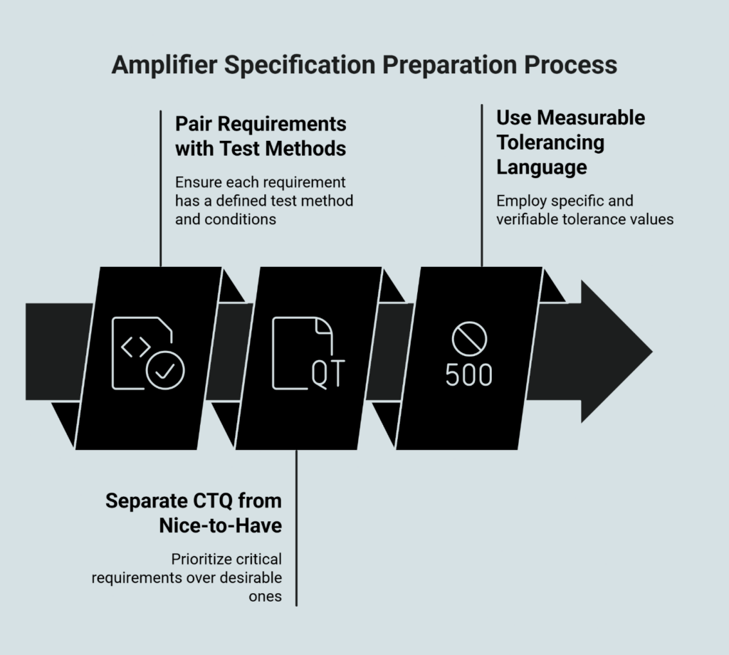
Pair every requirement with a test method and conditions. A power output spec without a defined load impedance, input frequency, and THD threshold is incomplete. A requirement without a test method becomes a debate. A test method without conditions becomes inconsistent. The factory will ask, or worse, assume.
Separate CTQ from nice-to-have. CTQ items drive yield, reliability, and warranty exposure. When requirements conflict—and they will—the factory needs a priority stack. If thermal margin and form factor collide, which wins? A long undifferentiated list forces the factory to guess priorities. Define the tie-break rule upfront.
Use tolerancing language that is measurable. “Tight tolerance” means nothing. ±0.1mm on a datum surface with a specified flatness callout means something a quality engineer can verify. When physical fit or thermal contact quality matters, tolerances must be inspectable, not aspirational.
What a Factory Should Return After DFM Review
A useful DFM integration outcome is not a vague “looks good.” After their review, you should receive a structured return package that supports fast decisions:
- DFM findings by subsystem covering electrical, mechanical, thermal, and test considerations with specific manufacturability risks identified
- A risk register documenting what could fail at scale and why, with severity rankings
- An ECO list containing proposed changes with rationale and verification plans for design modifications they recommend
- Open questions requiring stakeholder decisions on trade-offs, priorities, and constraints that need your engineering input
This output makes the ECO loop purposeful instead of chaotic, and it supports clean transitions into EVT/DVT/PVT gates.
Common Failure Modes and How to Prevent Them
| Problem | Why It Happens | Prevention in Handoff Package |
|---|---|---|
| Impossible or unmeasurable tolerances | Spec written for lab conditions, not production metrology | Review tolerances against factory measurement capability; use GD&T with explicit datum structure |
| Ambiguous test conditions | Pass/fail threshold defined without operating envelope | Include ambient temp, supply voltage, load, and input signal in every test spec |
| Uncontrolled component substitutions | BOM lists part numbers without alternates or “no substitute” flags | Explicitly flag critical components; define approval process for any substitution |
| Thermal strategy under-specified | Spec lists max junction temp without defining thermal interface, airflow, or ambient assumptions | Include thermal stack-up assumptions; define pre-tooling thermal expectations with correlation accuracy requirements |
| Golden sample illusion | One perfect unit becomes the “truth,” masking process drift | Define golden/limit sample rules and change-control governance |
Each failure mode traces back to a gap in the handoff package. The factory is not guessing maliciously—they’re filling silence with assumptions.
Frequently Asked Questions
How early should the DFM handoff happen?
Before tooling decisions and before validation schedules are locked. Early DFM reduces late ECO churn because risks are surfaced when changes are still inexpensive.
Is a longer document better?
Not necessarily. Clear CTQ prioritization and measurable acceptance criteria usually matter more than page count. The goal is not to over-document—it’s to make the program inspectable, assemblable, and change-controlled.
What if the program is still evolving?
Use revision control and decision rules. A controlled “known-unknowns” list is better than silent ambiguity. Define what is fixed versus flexible (cost, size, topology, protections) so DFM review doesn’t propose changes that violate non-negotiables.
Should the handoff include standards references?
When quality system expectations or tolerancing concepts need shared framing, authoritative references help establish common language between your team and the factory.
Run a DFM Review Kickoff with Your OEM
Before your first kickoff meeting, send the complete handoff package 48–72 hours in advance. This gives the factory engineering team time to review and prepare specific questions rather than discovering gaps in real-time.
Pre-kickoff checklist:
- Requirements matrix with all columns populated
- Electrical and mechanical CAD packages uploaded to shared repository
- Firmware build files with version documentation
- Draft test plan with proposed pass/fail thresholds
- Named approvers for ECO sign-off on both sides
Kickoff agenda decisions to lock:
- Confirm measurement methods and equipment for each CTQ parameter
- Identify any tolerances the factory cannot hold or measure
- Agree on first-article approval criteria and yield exit thresholds
- Establish revision control and ECO communication cadence
The output should be a shared DFM findings document with clear owners and target resolution dates.
For broader context on how this handoff fits within the full program lifecycle, see Understanding the OEM/ODM Manufacturing Process and Integrating DFM into the NPI Workflow. For process transparency around production flow and test stations, see Inside Our Amplifier Production Process.
Ready to discuss your next amplifier program? Contact our engineering team to schedule a DFM review kickoff, or explore our amplifier platform options to see what’s possible with a co-development partnership built on rigorous quality gates.
Our Editorial Process:
Our expert team uses AI tools to help organize and structure our initial drafts. Every piece is then extensively rewritten, fact-checked, and enriched with first-hand insights and experiences by expert humans on our Insights Team to ensure accuracy and clarity.
About the China Future Sound Insights Team:
The China Future Sound Insights Team is our dedicated engine for synthesizing complex topics into clear, helpful guides. While our content is thoroughly reviewed for clarity and accuracy, it is for informational purposes and may vary by project context, specifications, and manufacturing partners.