
📌 Key Takeaways
Design reviews before tooling locks prevent costly redesigns and protect your production quality from drifting away from your prototype.
- Lock Points Define “Early Enough”: Five specific freeze moments—PCB layout, mechanical design, test fixtures, supplier picks, and acceptance rules—mark when changes become expensive.
- Test Access Is a Design Choice: If you can’t probe, program, and measure the board after final assembly, you’ll discover quality problems in the field instead of on the line.
- Traceability Starts in Design: Serial numbers that link to test data and component lots must be built into the product from the start—not bolted on afterward.
- Containment Plans Beat Crisis Responses: Written stop-ship triggers and quarantine rules should exist before production starts, not get invented during a problem.
- Demand Artifacts, Not Promises: When evaluating factory partners, ask to see actual sample reports, change-control documents, and traceability demos—not just verbal assurances.
Move quality decisions upstream, and the factory executes your specs instead of guessing your intent.
Private-label audio product leaders will find a practical audit framework here, preparing them for the detailed lock-point and review guidance that follows.
~ ~ ~ ~ ~ ~ ~ ~ ~ ~ ~ ~ ~ ~ ~ ~ ~ ~ ~ ~ ~ ~ ~ ~ ~ ~ ~ ~ ~ ~ ~ ~ ~ ~ ~ ~ ~ ~ ~ ~ ~ ~ ~ ~ ~ ~ ~ ~ ~ ~ ~
The warranty escalation never starts with sound quality. It starts with a question nobody can answer fast enough: “Which build variant shipped?” If you can’t trace serial numbers back to a controlled design, a controlled process, and a controlled change log, you don’t have a quality problem—you have a governance problem.
DFM only saves money when it’s treated as a phase-gate deliverable before lock points—and when it’s integrated with testability, traceability, and change control. Otherwise, “cost optimization” becomes late churn, mixed builds, and production drift that shows up months later as field inconsistency. The National Institute of Standards and Technology (NIST) formally defines DFM as the practice of designing products to optimize manufacturing ease and economic efficiency, emphasizing that early intervention during the design stage is critical. Treating DFM as an upstream governance tool prevents the costly reality of addressing problems after the factory has already committed.
For private-label audio product leaders, this distinction matters. You’ve seen how “good prototype, bad production” erodes margins, slips timelines, and jeopardizes the market trust established over previous product cycles. The prototype passed every test. The first production run? Three redesign requests in six weeks. The fix isn’t working harder during ramp. It’s moving DFM upstream, treating it as launch-risk governance rather than late-stage optimization.
This guide shows where DFM fits inside EVT/DVT/PVT, defines the five lock points that make “before tooling” concrete, and gives you a five-point audit to execute manufacturability audits that stabilize yield and baseline costs without compromising acoustic performance.
Where DFM Fits in EVT → DVT → PVT (and Why PMs Should Care)
Most teams talk about EVT/DVT/PVT as engineering milestones. Product leaders should treat them as risk-buydown gates that progressively reduce uncertainty: engineering feasibility (EVT), design intent validation (DVT), and production readiness (PVT). Instrumental’s guide to stage gates provides a useful overview of these phases.
DFM is the connective tissue across those gates—but its highest ROI comes before you lock irreversible decisions. Think of DFM as the gate that converts a functional prototype into a buildable, auditable blueprint. The architect’s drawing becomes the engineer’s construction document. Without that translation step, you’re asking a factory to interpret your intent rather than execute your specification.
In a typical amplifier program:
EVT: You’re proving the architecture and core performance. DFM here is about early warnings—thermal strategy realism, connector accessibility, BOM risk.
DVT: You’re validating the intended design. DFM becomes hard constraints—assembly sequence, tolerance stack-ups, programming access, test coverage.
PVT: You’re validating the factory system. DFM becomes process control—fixtures, work instructions, traceability routes, containment triggers.
If you wait until PVT to “do DFM,” you’re not doing DFM—you’re doing damage control. For product managers, this means DFM isn’t optional overhead. It’s the control point that prevents redesign loops, mixed builds, and the quality drift that shows up three months after SOP.
What “Before Tooling” Really Means (The Five Lock Points)
“Before tooling” isn’t a calendar date. It’s a set of lock points—moments after which changes get exponentially more expensive, slower, and riskier. Treat these as explicit decision boundaries:
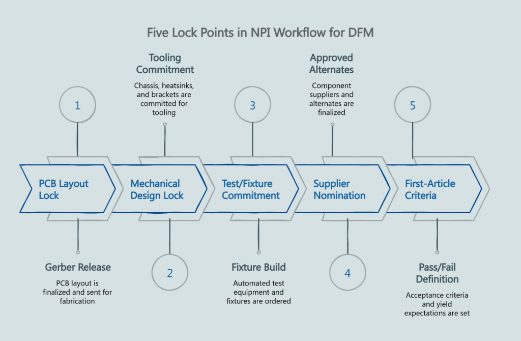
1. PCB Layout Lock Once the Gerber files release to fabrication, changing trace routing, component placement, or layer stackup requires a board respin. That means new tooling charges, qualification cycles, and schedule slip. Test points, programming access, and rework access are largely baked in after this freeze. DFM inputs for electronics must be complete before this lock.
2. Mechanical Design Lock (Chassis, Heatsinks, Brackets, Cosmetics) Chassis, heatsinks, and brackets require injection molds or extrusion dies. These tools are expensive and slow to modify. After this lock, your assembly sequence, cable routing realities, and tolerance stack-ups become physical constraints. Tolerance stackups, assembly access, and thermal interface decisions must be locked before tooling cuts.
3. Test/Fixture Commitment Automated test equipment fixtures, programming jigs, and end-of-line stations are designed around the product. Once you commit to these fixtures, late access changes ripple into tooling rework and schedule slips. If the design changes after fixtures are built, you either rebuild the fixtures or accept reduced test coverage. Neither option is free.
4. Supplier Nomination and Approved Alternates Component alternates, approved vendor lists, and first-article acceptance criteria define what “good” looks like at scale. If alternates and substitutions aren’t engineered into the plan, supply turbulence becomes quality turbulence. Changing suppliers after nomination triggers requalification—and introduces the exact variability DFM is supposed to eliminate.
5. First-Article Criteria Definition If pass/fail limits, yield expectations, and ECO cut-in rules aren’t defined, you get “it passed once” logic instead of stable production logic. This lock point establishes the acceptance criteria that separate conforming product from nonconforming product.
A practical definition: DFM is “early enough” only if it can still influence these lock points. If your DFM review doesn’t explicitly address all five, it’s incomplete. Each boundary represents cost and schedule that becomes fixed once you cross it.
DFM Inputs Before PCB Layout Lock (Electronics)
For an amplifier, electronics DFM is not just “can the PCB be assembled?” It’s whether the design will be buildable, testable, and diagnosable at scale. The DFM inputs that drive yield in amplifier programs often trace back to decisions made—or missed—at this stage.
Design for Test (DFT) and Access Adequate test points for critical nets are essential. Programming and debug access must still exist after final mechanical assembly. Clear end-of-line coverage goals define what failures you intend to catch in production versus in burn-in or aging. Can the board be probed, programmed, and measured without custom fixturing gymnastics? Accessible test points reduce fixture cost and improve fault coverage. Programming headers that work with standard programmers save development time.
Thermal Margin Decisions Power dissipation paths are hard to change after layout. Copper pours, via stitching, and component spacing affect junction temperatures—and those temperatures affect long-term reliability. Thermal choices made at this stage compound through the entire product lifecycle.
Component and Package Selection Fine-pitch BGAs yield differently than QFNs. Moisture-sensitive components require handling controls. Obsolescence-prone parts create supply risk. DFM evaluates whether the BOM is buildable at volume—not just functional on a bench.
Assembly Touch Time and Rework Risk Connector placement that avoids awkward insertion angles matters. Harness routing that doesn’t require “craft skill” to meet cosmetic requirements keeps labor costs predictable. Parts that are easy to verify—polarity, orientation, labeling—without slowing the line prevent bottlenecks.
BOM Resilience Engineered, Not Hoped For Approved alternates should be identified before shortages force substitutions. Component lifecycle and availability deserve review as a risk map—what can become an ECO under schedule pressure? This is where many teams accidentally create future drift: they optimize the prototype, then discover the production test strategy can’t reliably detect the failure modes they actually see at volume.
DFT/DFX Alignment Design for Test and broader Design for Excellence principles overlap with DFM. The question isn’t just “can we build it?” but “can we verify what we built?” If the answer is no, you’ll discover quality problems in the field instead of on the line.
DFM Inputs Before Mechanical Tooling (Chassis, Heatsinks, Brackets)
Mechanical decisions often become the hidden driver of schedule risk because they constrain everything else: assembly order, reworkability, thermal consistency, and even test access.
Thermal Path Realism Heatsink interface consistency—flatness, interface materials, pressure uniformity—must be validated. Thermal stack-up sensitivity means small tolerance changes can cause large thermal changes. A thermal interface that works with hand-applied paste may fail with automated dispensing. Mechanical DFM ensures the thermal design from simulation translates to the assembly process.
Tolerance Stackup and Cosmetic Risk Tight tolerances cost money. Loose tolerances create fit problems. DFM quantifies the stackup and identifies where cosmetic standards—gap uniformity, flush surfaces—conflict with realistic manufacturing variation. Resolving these conflicts before tooling prevents the “it looks wrong but measures in spec” arguments that delay shipments.
Design for Assembly Every screw adds labor time. Every hidden connector adds rework risk. Fastener strategy—count, types, access, torque control practicality—deserves scrutiny. Harness routing should be repeatable without forcing “bend-to-fit” behavior. Connector access must remain stable after the enclosure is assembled. Can the unit be assembled without flipping it six times? Can a technician reach the connector without removing three other subassemblies?
Serviceability and Diagnosability How will field failures get diagnosed? Can you isolate a failure without destructive teardown? Are likely rework operations feasible without cosmetic damage? If the only way to access a suspect component is destructive teardown, field service costs escalate and diagnostic efficiency collapses. DFM considers the service path alongside the assembly path.
If your mechanical design forces awkward assembly or blocked access, you’ll pay for it later in labor, rework, and variable outcomes that are hard to contain.
DFM as Process Design: Test, Traceability, Work Instructions
DFM isn’t only about the geometry of parts. It’s about whether the manufacturing system can control variation.
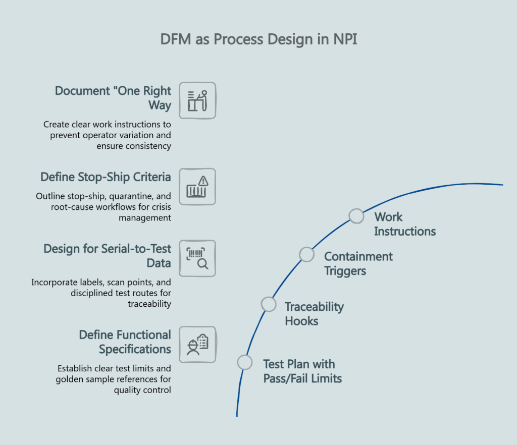
Test Plan with Pass/Fail Limits Functional specifications define what the product should do. Test limits define what “pass” means on the production line. End-of-line testing isn’t just a station; it’s a control mechanism that defines acceptable limits and prevents drift. Without explicit limits tied to golden sample references, yield becomes subjective—and quality drift becomes invisible until customers complain.
Traceability Hooks If you want traceability—serial-to-test data, serial-to-lot—the design must support labels, scan points, and a disciplined test route. Traceability isn’t an afterthought bolted onto finished assemblies. It’s a design requirement that DFM must address. Barcode or QR binding of test data to serial numbers requires labeling locations, scanning points, and test-route discipline built into the product.
Containment Triggers What happens when something goes wrong? Stop-ship criteria, quarantine procedures, and root-cause workflows should be defined before SOP—not invented during a crisis. DFM outputs feed directly into engineering change control processes that govern how changes cut in and what stock disposition rules apply. ISO 9001 quality management principles emphasize a framework for consistency and meeting customer expectations—useful as a governance lens when evaluating whether a factory system can actually sustain control.
Work Instructions Process capability becomes a design requirement when DFM is done right. If a step requires operator skill that varies shift-to-shift, the design should be simplified or the process should be automated. Work instructions document the “one right way” that prevents variation.
A simple heuristic: if your “quality plan” is mostly inspection after the fact, you’re accepting drift and hoping to catch it. DFM should reduce the probability of drift in the first place.
How to Run a Cross-Functional DFM Review (and Exit Criteria)
Treat DFM as a gate with sign-off, not a meeting. A DFM review isn’t a design engineering checkpoint. It’s a cross-functional gate that requires participation from everyone who will be affected by the decisions being locked.
Who Must Attend Product management, electrical engineering, mechanical engineering, quality assurance, procurement/sourcing, and manufacturing engineering—plus the OEM/ODM’s manufacturing and quality counterparts. If any of these functions is absent, the review is incomplete. Each brings constraints the others may not see.
Required Inputs The DFM data package should include: BOM with risk flags (long lead, sole source, EOL), CAD models and drawings with critical dimensions and tolerances, PCB layout with test point map (or constraints if layout is not final), draft test plan with coverage goals and pass/fail limits, tooling assumptions and quotes (what is being cut/committed, and when), first-article acceptance criteria, and draft ECO/change control approach (how changes are approved and cut in).
Output Artifacts A successful DFM review produces: a DFM report documenting findings and dispositions with issues categorized by severity and lock point impacted, an action list with owners and due dates, explicit lock-point boundaries (what’s frozen versus what’s still open), ECO rules for changes after lock, test strategy reviewed for coverage and access, and traceability plan validated (what data is captured and how it binds to serials).
Exit Criteria The review passes when all critical findings are resolved or have approved mitigation plans, lock-point boundaries are documented and agreed, and the cross-functional team signs off. If you can’t get sign-off, you’re not ready to release tooling.
For programs following gated RFQ-to-SOP timelines, the DFM review is the gate before tooling release—not a parallel activity that runs alongside it.
The 5-Point DFM Audit
Use this checklist to run manufacturability audits that stabilize yield and baseline costs without compromising quality. Each question targets a specific risk; each answer should be backed by evidence.
1. What decisions are we about to lock (PCB, tooling, fixtures), and what is the explicit “no-change” boundary after each lock?
Why it matters: If you can’t name the lock point, you can’t control late cost.
Evidence to request: A one-page lock-point map (PCB lock / mechanical lock / fixture commit) with allowed versus disallowed changes. A sample ECO cut-in rule document showing how changes are versioned, approved, and separated from old builds. Change-control policy defining what requires a formal ECO after each freeze.
2. Does the design minimize manual touch time and rework risk (connector access, screw counts, wiring harnesses, thermal interface, labeling)?
Why it matters: Labor and rework are the hidden cost multipliers.
Evidence to request: Assembly sequence document with major steps and touch points. Time study or cycle time estimate. Photos or examples of fixture concepts or workstation layout assumptions. Rework rate history from similar builds (categories, not marketing promises).
3. Is the design testable at scale (test points, programming access, EOL coverage, pass/fail limits, golden sample reference)?
Why it matters: If you can’t measure it, you can’t control drift.
Evidence to request: Test coverage analysis with draft end-of-line test plan, coverage goals, and pass/fail limits. Golden sample sign-off documentation showing how it’s stored, validated, and used. Pass/fail limit table with measurement method. Statement of programming access and how it’s achieved in the final assembly state.
4. Is supply risk engineered out (approved alternates, component availability plan, ECO cut-in plan, lot control)?
Why it matters: Shortages and substitutions trigger quality drift if unmanaged.
Evidence to request: Approved alternate list with qualification status (and who approves substitutions). Component availability forecast. ECO cut-in rules including inventory disposition rules. Lot control and material trace approach for critical components.
5. Is the containment plan defined before SOP (stop-ship triggers, quarantine, root-cause workflow, traceability logs)?
Why it matters: Containment prevents small issues from becoming field failures.
Evidence to request: Written stop-ship and quarantine triggers. Containment procedure document with root-cause workflow (roles, timelines, 8D/CAPA expectations). Traceability system demonstration showing what fields are captured and how they bind to serial numbers. Stop-ship criteria matrix.
Common Failure Modes When DFM Is Skipped
These aren’t theoretical. They’re the predictable outcomes of missing governance—and the lived experience of product leaders who’ve survived “good prototype, bad production” and vowed never to repeat it.
The Redesign Loop A producibility issue surfaces during pilot builds. Engineering scrambles to fix it. The fix requires a board respin or tooling modification. The schedule slips. The next pilot uncovers another issue. Repeat until the launch window closes.
Mixed Builds A late ECO cuts in mid-production. Some units have the old design; some have the new. Serialization doesn’t distinguish them. Field failures become impossible to diagnose because you don’t know which configuration shipped. Without cut-in rules, field inconsistency becomes hard to trace.
Quality Drift The first articles looked great. Production month three looks different. Without golden sample discipline and pass/fail limits tied to traceability, drift accumulates invisibly—until field returns critically compress hardware margins and trigger warranty escalations. Production control limits were never defined, so “successful prototypes” became inconsistent production units.
“It Passed Once” Fallacy A marginal design passes prototype testing because hand-built units get extra attention. Volume production, with its natural variation, pushes marginal designs into failure. DFM catches marginality before it becomes yield loss.
What to Ask Your OEM/ODM Partner (RFQ / Supplier Vetting)
DFM becomes procurement leverage when you demand artifacts instead of promises. If you want DFM to be real, you must be able to audit it. When evaluating an amplifier production partner, ask:
“Show me your DFM deliverables and sign-off cadence.” A capable partner has a documented DFM process with templates, checklists, and review gates. Ask for a redacted sample from a prior program. If they can’t show you what their DFM report looks like, they’re improvising.
“What are your DFM gate exit criteria before PCB lock, mechanical lock, and fixture commitment?” The answer reveals whether they treat DFM as a gate or a checkbox.
“How do you link DFM outputs to golden sample management?” The golden sample should reflect DFM decisions—test limits, cosmetic standards, build configuration. If the golden sample is disconnected from DFM, consistency control is wishful thinking. Ask how often it’s re-validated.
“What’s your ECO process and cut-in discipline?” Changes after lock should flow through formal engineering change control with traceability. Ask for an example of how they handled a mid-production change and what stock disposition rules applied. Walk through their ECO approval and cut-in plan—including how they prevent mixed builds.
“Can you demonstrate traceability from serial number to component lot?” Barcode or QR binding should let you trace any unit back to its build date, test results, and component lots. Ask for the minimum traceability dataset. If containment requires this data and it doesn’t exist, small problems become large ones.
“What are your written stop-ship/quarantine triggers and escalation path?” The answer shows whether containment is documented or improvised.
For a comprehensive list of requirements, reference what an RFQ should include when engaging OEM/ODM partners.
Turning DFM into Launch Confidence
DFM isn’t about making things cheaper. It’s about making decisions visible before they become permanent.
When DFM sits in its proper place—after functional validation, before tooling lock—you replace the anxiety of “will production match the prototype?” with documented controls that answer that question before you commit capital. The audit questions become RFQ requirements. The lock points become schedule milestones. The exit criteria become sign-off gates.
That’s how product leaders move from surviving redesign loops to preventing them. While the initial architecture must still meet rigorous acoustic benchmarks, this framework ensures the factory’s mass-production capabilities are equally validated.
Ready to discuss your next program?
For a structured DFM gate aligned with your NPI timeline, contact our engineering team:
Phone: +86 139 6730 8635
Email: hu@chinafuturesound.com
Disclaimer: This content is for informational purposes and should not replace professional manufacturing or quality assurance advice specific to your program requirements.
Our Editorial Process:
Our expert team uses AI tools to help organize and structure our initial drafts. Every piece is then extensively rewritten, fact-checked, and enriched with first-hand insights and experiences by expert humans on our Insights Team to ensure accuracy and clarity.
About the China Future Sound Insights Team
The China Future Sound Insights Team is our dedicated engine for synthesizing complex topics into clear, helpful guides. While our content is thoroughly reviewed for clarity and accuracy, it is for informational purposes and should not replace professional advice.