📌 Key Takeaways
Heat kills schedules—thermal failures discovered after tooling lock design parameters that can’t accommodate proper safety margins.
- Pre-Tooling Gates Prevent Expensive Surprises: Defining thermal margins, derating policies, and acceptance thresholds before tooling transforms thermal performance from a validation crisis into a design input.
- Correlation Validates Reality: Thermal simulations mean nothing without chamber testing that reconciles predictions against measured data within ±5-10°C—documented boundary conditions and variance reports become contractible proof.
- HALT Finds Weaknesses, HASS Catches Defects: Highly Accelerated Life Testing surfaces design vulnerabilities before production while stress screening eliminates manufacturing variation that standard tests miss.
- Protection Circuits Are Safety Nets, Not Solutions: Over-temperature and over-current protections that activate during normal use signal under-margined thermal design—thresholds should guard against abnormal conditions, not compensate for inadequate heat management.
- Golden Samples and Traceability Enable Rapid Response: Barcode-linked test data connecting each unit to component lots, manufacturing windows, and performance baselines supports targeted recalls when field patterns reveal systematic thermal issues.
Set these expectations in RFQ annexes and contract statements of work—payment milestones tied to correlation reports, HALT completion, and acceptance artifacts make thermal reliability legally binding rather than aspirational.
Brand owners, product leaders, and quality executives managing OEM amplifier programs will establish their technical framework here, preparing them for the supplier evaluation and program execution details that follow.
The conference room goes quiet. Your engineering team has just discovered that the amplifier pilot units—which passed every bench test last month—are now failing intermittently under sustained load during mass production validation. The root cause? Thermal margins that looked adequate in controlled lab conditions prove insufficient when production units run hot inside real-world enclosures with restricted airflow.
This scenario plays out more often than it should in OEM amplifier programs. The problem isn’t a lack of testing; it’s that thermal and reliability expectations were negotiated too late in the development cycle, after tooling decisions locked in design parameters that can’t accommodate the necessary safety margins. By the time heat-related issues surface, your options narrow to expensive rework, schedule delays, or accepting elevated warranty risk.
Setting measurable thermal and reliability expectations before tooling gives your OEM amplifier supplier’s design, test, and QMS processes the specifications they need to hit start of production without heat-related surprises. This means defining margin targets, derating policies, a right-sized HALT/HASS plan, and acceptance thresholds early enough that they inform—not retrofit—the design.
Why Thermal and Reliability Gates Belong Before Tooling
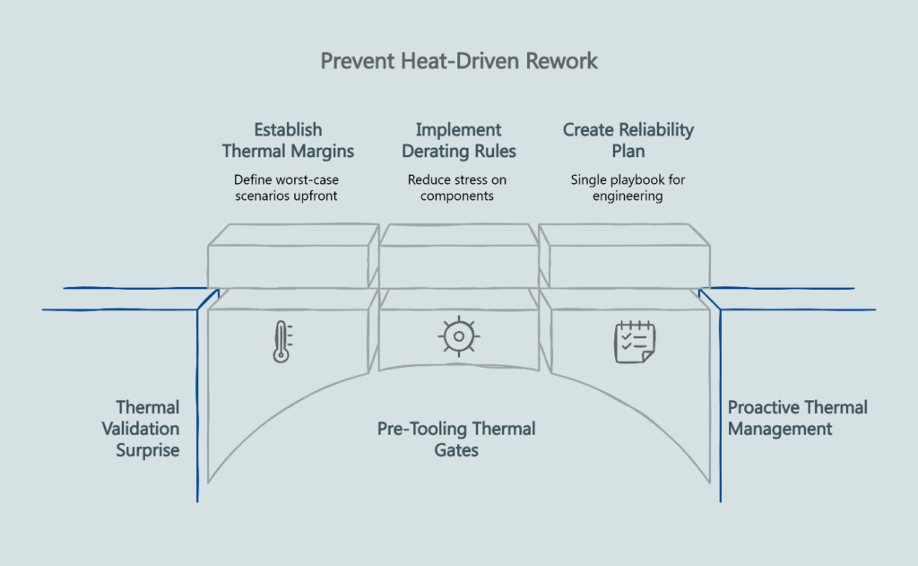
Pre-tooling decisions prevent heat-driven rework and warranty exposure by making thermal performance a design input rather than a validation surprise. Heat acts as a silent schedule killer in electronics programs—prototypes pass on the bench, then fail in pilot or early mass production after thermal soak, vibration exposure, or stacked tolerances reveal weaknesses that weren’t apparent in controlled testing.
Consider a typical scenario: A brand owner finalizes amplifier specifications with a supplier, approves initial prototypes, and moves into tooling. The supplier conducts thermal testing on engineering samples in an open-air bench environment at 25°C ambient temperature. Results look promising—junction temperatures stay within acceptable limits during standard test sequences.
Production ramp begins six months later. Field units ship in sealed automotive enclosures where ambient temperatures reach 65°C, and acoustic loads demand sustained output for hours at highway speeds. Within weeks, warranty returns spike due to thermal shutdowns and premature component failures. The supplier’s thermal testing wasn’t wrong; it simply measured the wrong conditions because nobody specified worst-case scenarios before design freeze.
Establishing thermal margins, derating rules, and a reliability plan up front gives engineering and manufacturing a single playbook. This approach aligns with hazard-based safety expectations for audio and ICT equipment under standards like IEC 62368–1, which addresses thermal safeguards as part of comprehensive equipment safety requirements.
The factory evaluation checklist your sourcing team uses should verify that suppliers have thermal chambers and reliability test capabilities. But capability means nothing without contractible targets that define what “passing” looks like in your specific use environment.
Define Your Thermal Strategy: Targets, Derating, and Correlation
Thermal Contexts That Drive Design Decisions
Amplifier thermal performance depends on multiple interacting variables that your supplier needs spelled out explicitly. Start by documenting three thermal contexts for your program.
First, define ambient temperature ranges. A marine amplifier faces salt-laden air at temperatures from -20°C to 85°C. A home theater receiver operates in climate-controlled rooms between 15°C and 30°C. Your supplier can’t optimize heat-sinking or select appropriate component temperature grades without knowing these boundaries.
Second, specify worst-case operating conditions. This means sustained output power levels, duty cycles, and load impedances that represent the thermal stress your product must survive. Convert these use environment requirements into junction-temperature and case-temperature budgets for your hottest devices—output stages, power supply switching components, rectifiers, and linear regulators. If your automotive amplifier needs to deliver 75 watts per channel into 4-ohm speakers for three continuous hours in a trunk where ambient hits 75°C, those thermal budgets become the design requirement—not a 30-minute bench test at 25°C.
Third, establish delta-T budgets for critical components. Junction-to-case thermal resistance for power semiconductors, board-to-ambient thermal paths, and enclosure ventilation restrictions all contribute to the temperature rise above ambient. These deltas compound, and each degree matters when you’re designing for reliability over a 5-year warranty period.
Component and Assembly Derating Policy
Derating—operating components below their maximum rated specifications—directly reduces field failure rates. Conservative operating margins extend component lifespan and improve system reliability, a principle documented extensively in NASA’s EEE-INST-002 guidelines for electronic parts derating in high-reliability applications.
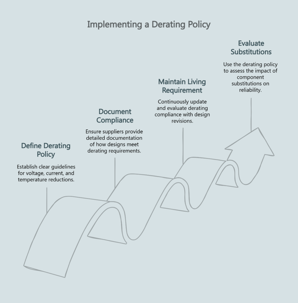
Your derating policy should specify percentage reductions from component datasheets for voltage, current, and temperature. A common approach for consumer electronics establishes 80% voltage derating for electrolytic capacitors, 70% current derating for inductors, and operation at no more than 80% of maximum junction temperature for semiconductors.
The supplier must document how the design meets these derating requirements. This isn’t a one-time calculation—it’s a living requirement that travels with design revisions. When a supplier proposes a component substitution to address supply chain constraints, the derating policy provides the framework for evaluating whether the change maintains reliability margins.
Simulation to Chamber Correlation Plan
Thermal simulation tools predict heat distribution across PCB assemblies and estimate junction temperatures under load. These predictions guide initial design decisions about copper weight, component placement, and heat-sinking requirements. But simulation is only as useful as its match to reality.
A correlation plan defines how your supplier will validate predictions against measured data from thermal chamber testing. Require the supplier to document boundary conditions—loads, ambient temperature, airflow assumptions, and heat sink interfaces. They should build and execute a correlation plan: simulate thermal performance, test physical assemblies in chambers at defined loads following JEDEC JESD51 thermal characterization standards, and reconcile results within an agreed delta.
Specify acceptable variance between predicted and measured values—typically ±5°C to ±10°C for junction temperatures depending on design complexity—and require a formal report documenting the correlation before moving to tooling. The correlation artifact should include annotated thermal plots, chamber setup photos with thermocouple placement, and a variance summary that explains any discrepancies.
The DFM specifications that most affect yield include thermal design margins. Locking these margins through a validated correlation process prevents optimistic simulations from understating real-world thermal stress.
Program Reliability Plan: HALT, HASS, and Acceptance Thresholds
What HALT and HASS Accomplish
Highly Accelerated Life Testing (HALT) and Highly Accelerated Stress Screening (HASS) serve distinct purposes in amplifier development and production. Research from the Center for Advanced Life Cycle Engineering at the University of Maryland demonstrates how HALT surfaces early-life failure mechanisms by applying extreme environmental and operational stresses to engineering samples before production tooling.
HALT explores design limits by combining thermal cycling, vibration, and voltage margining beyond normal operating ranges. The goal is finding failure modes—mechanisms that would appear as premature field failures—during development when fixes are still economically feasible. A properly executed HALT program on amplifier prototypes typically reveals three to five design vulnerabilities that wouldn’t show up in standard qualification testing.
HASS applies production-relevant stresses to every manufactured unit or a statistically significant sample to screen out manufacturing defects before shipping. Where HALT finds design problems, HASS catches process variation—cold solder joints, contaminated assemblies, marginally seated connectors.
Right-Sizing Stress Profiles and Sample Sizes
Amplifier programs need HALT plans tailored to their specific use environment and risk tolerance. Automotive applications demand more aggressive stress profiles than residential audio equipment because the consequences of field failures differ substantially.
Your reliability plan should specify temperature cycling ranges, rates of change, vibration profiles, and electrical stress conditions for HALT. Start with small samples to explore design limits, then back off to non-destructive screens for HASS and ongoing production stress screening. Sample sizes for HALT depend on production volumes and acceptable risk levels—typically 5 to 10 units, with failure analysis and design corrections triggering repeat testing.
For HASS, define whether you’re implementing 100% screening or sampling strategies, screen duration, acceptance criteria, and fallout disposition. A common approach screens 100% of production during initial ramp, transitioning to statistical sampling once process capability demonstrates stability through controlled limits on recoverable events and zero catastrophic failures.
Tying Reliability Testing to QMS and Exit Criteria
The reliability plan only delivers value when it connects to your supplier’s quality management system. Failures discovered during HALT or HASS must route through a documented corrective action and preventive action (CAPA) process with root cause analysis and design or process corrections.
Specify how failures get classified—typically A (critical safety/performance), B (major functional degradation), and C (minor cosmetic or parameter drift)—and the required actions for each category. Class A failures halt production pending corrective action. Class B failures may allow controlled shipping with expedited fixes. Class C findings feed continuous improvement without stopping the line.
Exit criteria define when your reliability testing phase completes successfully. This typically requires achieving target yield rates across multiple production lots, demonstrating acceptable fallout rates in HASS, and closing all open Class A and B CAPAs with verification testing.
Protection and Firmware Expectations
Treat Protection as a Safety Net, Not the Plan
Amplifiers incorporate multiple protection circuits—over-temperature warning (OTW), over-temperature protection (OTP), over-voltage protection (OVP), and over-current protection (OCP)—to prevent damage during abnormal operating conditions. These protections serve as essential safeguards, but they shouldn’t engage during normal use. If protection circuits activate regularly in typical operating scenarios, the underlying thermal design is under-margined.
Threshold Definition and Hysteresis Design
These protections require precisely defined behavior. At what junction temperature does OTW activate? What’s the hysteresis between warning and clear states to prevent chattering? How many degrees higher does OTP trigger a full shutdown? What’s the recovery process—automatic restart after cooldown, or manual power cycle?
Your supplier needs version-controlled threshold documentation that specifies not just trigger points but also timeout periods, retry logic, and logging behavior. When an amplifier enters thermal protection, the firmware should log the event with timestamp, temperature reading, and operating conditions. This data proves invaluable for failure analysis on warranty returns.
Regression Testing and Release Note Linkage
Protection thresholds often require adjustment during development as thermal characterization data improves understanding of actual operating margins. Every firmware release that modifies protection behavior must undergo regression testing that validates the new thresholds against your documented requirements.
Require that your supplier’s release notes explicitly call out changes to protection thresholds and link them to test reports demonstrating that the modified behavior meets specifications. This traceability prevents undocumented changes from introducing field failures.
The ATE and end-of-line testing framework should include functional verification of protection circuits at production test. Every amplifier leaving the line should demonstrate proper OTP activation and recovery, with persistent fault logs tied to test schemas that enable correlation between field returns and production data.
The Acceptance Package You Should Sign Before Tooling
Required Documents and Artifacts
Before authorizing tooling investment, your supplier should deliver a complete thermal and reliability design package for your review and sign-off. This package demonstrates that the design meets your specifications with measurable margins.
The package should include a thermal test plan specifying chamber setups, instrumentation, load conditions, and duration for all required test points. The correlation report documents agreement between simulation predictions and measured data from engineering samples. The reliability test plan details HALT procedures, HASS screening strategy, sample sizes, and acceptance thresholds.
Golden sample identification establishes traceability between approved design specifications and physical reference units. These samples—typically three to five units from pilot builds—represent the validated baseline for production. Any deviation from golden sample performance triggers investigation.
The traceability schema defines how production units connect to test data. Modern suppliers implement barcode or QR code systems linking each serialized amplifier to its manufacturing lot, component traceability, test results, and shipping records through integrated manufacturing execution systems (MES), warehouse management systems (WMS), and enterprise resource planning (ERP) platforms. This infrastructure supports FIFO inventory management and enables rapid, targeted recall execution when field failures reveal systematic problems.
Metrics, Yield Gates, and Defect Taxonomy
Acceptance criteria must include quantitative metrics that define success. Yield targets specify the percentage of units that must pass first-time testing at various production stages—typically 95% or higher after burn-in, 98% or higher at final functional test.
Burn-in policy defines whether you require elevated temperature operation for all units or a sampling strategy. High-reliability applications often specify 48 to 72 hours of burn-in at 60°C to 70°C ambient with cyclic loading to precipitate early-life failures before shipping.
The defect taxonomy classifies every possible failure mode as A, B, or C and prescribes corrective action timelines. This prevents disputes during production ramp about whether a specific issue justifies halting the line or represents acceptable process variation.
Supplier Capability Checklist: Equipment, QMS, and Data Access
Equipment and Lab Infrastructure
Your supplier needs specific test equipment to execute the thermal and reliability plan. Audio Precision analyzers provide the measurement accuracy required to characterize amplifier performance under thermal stress. An AD-1 dyno or equivalent system enables controlled dynamic loading during thermal testing. Programmable power supplies and electronic loads enable automated thermal cycling and life testing.
Thermal chambers with programmable profiles support both HALT and HASS operations. The chambers should accommodate full assemblies in their production enclosures, not just bare boards, because enclosure effects dominate real-world thermal behavior.
For amplifiers integrated into loudspeaker systems or acoustic assemblies, production consistency measurements using KLIPPEL QC systems help identify thermal-related performance drift by detecting impedance curve deviations and non-linear distortion changes that correlate with thermal stress.
QMS Cadence and CAPA Effectiveness
ISO 9001:2015 certification provides baseline assurance of documented quality processes, but the certificate alone doesn’t demonstrate thermal and reliability competence. Request CAPA history exemplars showing how the supplier identified, analyzed, and corrected thermal-related field failures from previous programs.
The supplier’s QMS should enforce IQC (incoming quality control), IPQC (in-process quality control), and FQC (final quality control) rhythms with documented inspection criteria at each gate. Thermal-related checks—verifying proper thermal paste application, heat sink attachment torque, and thermal pad compression—belong in these checklists.
Data Pipeline and Traceability System
The traceability infrastructure we discussed earlier enables rapid response when field failures reveal systematic problems. If warranty analysis shows that units manufactured during a specific two-week window exhibit elevated thermal shutdown rates, the integrated MES/WMS/ERP system identifies the component lots used during that period and supports targeted recall or proactive replacement programs.
This data pipeline must exist and function correctly before you depend on it during ramp. Ask for an equipment list with calibration status, reliability lab cadence, and sample data exports to confirm the infrastructure operates as documented.
The first-article approval criteria should verify that this traceability infrastructure operates correctly during pilot builds.
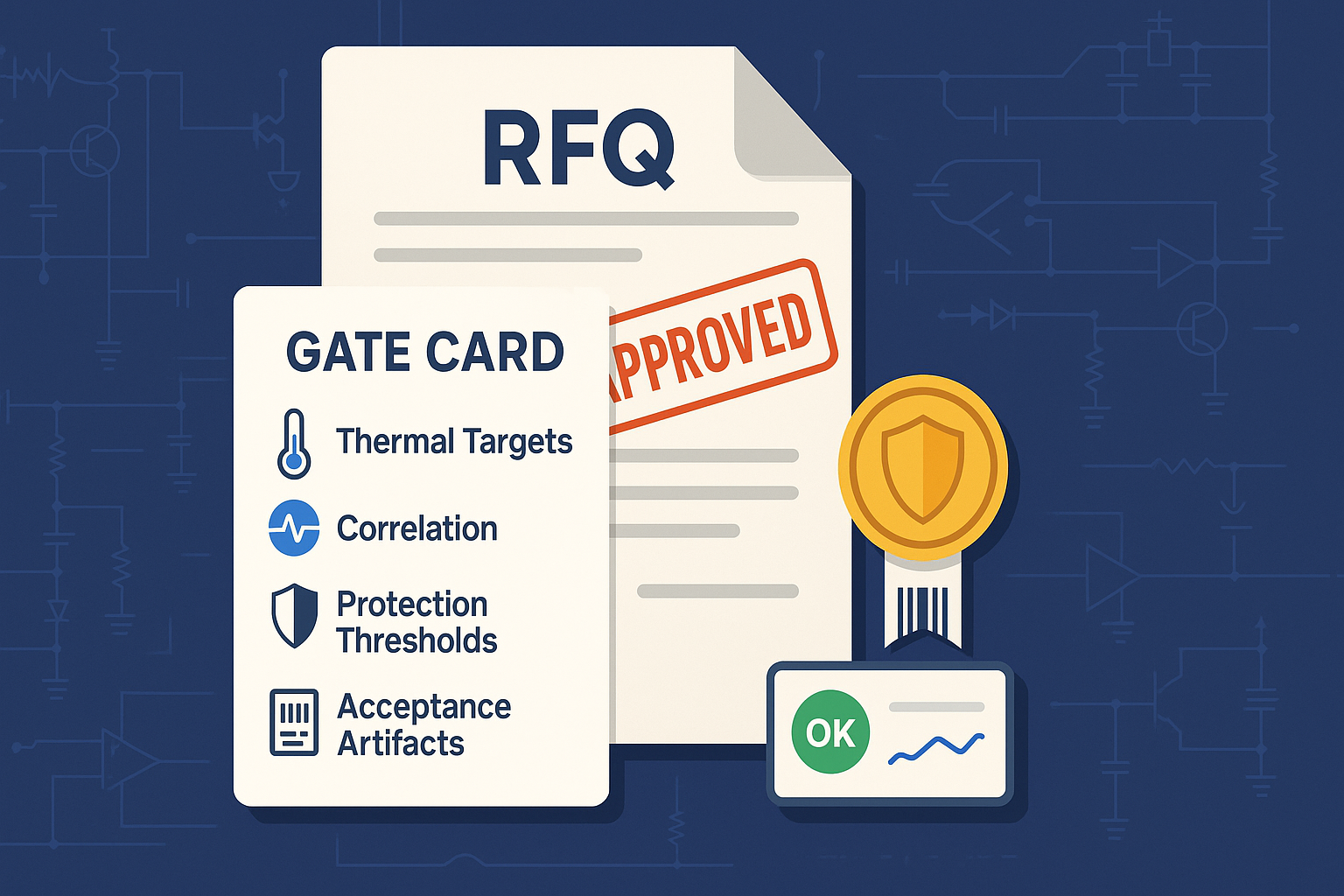
Thermal & Reliability Gate Card
To operationalize these expectations, you need a single-page reference that captures the critical decision points and required artifacts. The Gate Card organizes five essential elements.
Thermal Targets lists your documented ambient ranges, worst-case operating conditions, and acceptable delta-T budgets. It specifies component derating percentages and the required simulation-to-chamber correlation accuracy.
Reliability Test Plan summarizes your HALT stress profiles, sample sizes, HASS screening strategy, and the defect classification taxonomy with associated CAPA routing rules.
Protection Thresholds documents the OTW/OTP/OVP/OCP trigger points, hysteresis values, and timeout/retry logic your firmware must implement. It requires version control and regression test linkage for any threshold modifications.
Acceptance Artifacts identifies the documents and metrics you’ll verify before authorizing tooling: test plans, correlation reports, golden sample IDs, traceability schema, yield gates, and burn-in policy.
Supplier Capability Proof lists the QMS certification, test equipment inventory, and data pipeline capabilities you require as table stakes for program execution.
This Gate Card serves multiple purposes. Attach it to RFQ packages so potential suppliers understand thermal and reliability expectations during the quoting process. Reference it in contract statements of work to make these requirements legally binding. Use it as a go/no-go checklist during design reviews before releasing tooling authorization.
The card format supports multiple distribution channels. Export it as a PDF for email and document management systems. Reformat the five blocks as a LinkedIn carousel to educate your procurement team and broader industry network about professional supplier evaluation practices. Convert key decision points into a 60-second explainer video for internal training. Render the requirement matrix as a presentation graphic for executive briefings on program risk management.
What to Do Next
These thermal and reliability expectations become actionable when you integrate them into your supplier engagement process at three specific touchpoints.
During RFQ development, append the Gate Card as an annex to your technical specifications. Require suppliers to respond with specific evidence of capability for each element—not just “yes, we can do this” acknowledgments, but documented proof of equipment access, QMS procedures, and prior program examples.
Contract negotiation represents your opportunity to make these expectations legally binding. The statement of work should reference the Gate Card requirements and specify deliverable formats, review checkpoints, and acceptance criteria. Payment milestones can link to completion of specific thermal and reliability gates—correlation report approval, HALT completion, golden sample sign-off.
Design reviews throughout the development cycle return to these base requirements. When your supplier proposes component changes or design optimizations, evaluate them against the derating policy and thermal margin targets you established. The framework you’ve built ensures that engineering decisions maintain the reliability posture you need.
The DFM-to-ramp framework your supplier follows should incorporate these thermal and reliability gates as mandatory checkpoints. Programs that treat thermal validation as a post-tooling verification step consistently encounter expensive surprises. Programs that build thermal and reliability requirements into the design foundation from day one reach mass production on schedule with predictable warranty performance.
Disclaimer: This article provides general information about pre-tooling thermal and reliability expectations for OEM amplifier programs for educational purposes. Individual circumstances vary significantly based on factors like use environment (automotive/marine/pro audio), enclosure and heat-sinking, duty cycle and output loading, input voltage variation, acoustic load/impedance behavior, regulatory regime, target failure rate and warranty period, and ambient conditions. For personalized guidance tailored to your program’s risk tolerance and supplier capability, it is recommended to consult with a qualified professional.
Our Editorial Process
We prioritize accuracy, clarity, and real-world usefulness. Articles are reviewed for structure, terminology consistency, and alignment with our B2B content guidelines before publishing.
About the China Future Sound Insights Team
The China Future Sound Insights Team distills complex manufacturing topics into clear, helpful guides. Reviewed for clarity and accuracy; informational only, not a substitute for professional advice.