📌 Key Takeaways
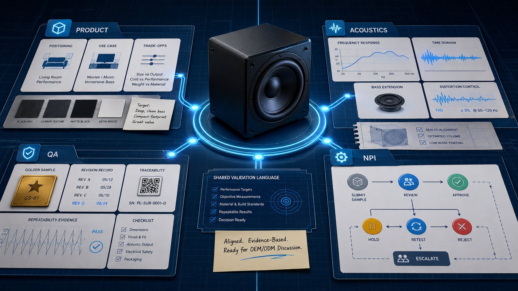
A golden sample proves your amplifier can work—not that 5,000 units will work when components, operators, and fixtures vary at scale.
- Golden Samples Capture One Moment: They validate a design under controlled conditions but miss the variation that high-volume production introduces over time.
- Component Drift Stays “In Spec” Yet Fails: Vendors may swap parts or ship different tolerance bins—both within limits, but the system-level behavior shifts enough to cause batch failures.
- Layered Quality Gates Catch Different Problems: IQC stops bad parts from entering, IPQC monitors process stability, and FQC tests finished units—no single gate is enough alone.
- Traceability Turns Days of Investigation into Hours: Linking serial numbers to component lots, test routes, and results lets teams isolate root causes fast when failures appear.
- Governance Beats Switching Factories: Chasing a new supplier won’t fix drift if the underlying controls are missing—process discipline prevents problems that inspection alone cannot catch.
Process control, not one perfect unit, separates successful launches from warranty nightmares.
Sourcing directors and product managers overseeing amplifier programs will find a practical framework for preventing scale-up failures, preparing them for the operational commitments detailed below.
~ ~ ~ ~ ~ ~ ~ ~ ~ ~ ~ ~ ~ ~ ~ ~ ~ ~ ~ ~ ~ ~ ~ ~ ~ ~ ~ ~ ~ ~ ~ ~ ~ ~ ~ ~ ~ ~ ~ ~ ~ ~ ~ ~ ~ ~ ~ ~ ~ ~ ~ ~
The batch report lands. Another failure.
It’s 9:00 AM on a Tuesday, and a Sourcing Director is staring at thermal test results that should have been routine. The Q4 product launch—the one the entire program has been building toward—is now dangerously behind schedule. The amplifiers passed EVT. They passed the golden sample approval. So why are units failing in volume production?
This is the question that haunts audio equipment programs, and the answer is almost never “bad design.” The answer is component drift—the silent, incremental divergence between what you approved and what actually gets assembled at scale. A golden sample proves capability once. It does not prove ongoing process control. And that distinction is the difference between a successful launch and a warranty crisis.
Why the Golden Sample Stops Working at Scale
A golden sample is a snapshot, not a movie. It captures one unit, built under controlled conditions, with hand-picked components from a single lot. When engineering signs off on that sample, they’re confirming that the design can work. They are not confirming that 5,000 units will behave identically three months later when production scales.
Scaling introduces variation at every stage. Components arrive from different vendor lots with different tolerance bins. Operators rotate shifts. Fixtures wear. Reflow oven profiles drift with ambient temperature changes. Each variable is minor in isolation. In combination, they compound.
The tipping point occurs when programs transition from pilot runs to high-volume batches. A pilot run of 200 units might use components from a single reel, assembled by one trained operator, with fresh fixtures. A production run of 5,000 units pulls from multiple reels, multiple shifts, and fixtures that have seen thousands of cycles. The golden sample cannot predict this environment because it was never exposed to it.
This is why relying solely on a golden sample creates a trap—it generates false confidence precisely when programs need rigorous process control. Standards-based quality management emphasizes consistent processes, defined acceptance criteria, and controlled change—not reliance on a single exemplar unit. The ISO 9001:2015 quality management framework and its foundational QMS principles reinforce this point: scale quality requires process control, not unit comparison.
What Component Drift Actually Looks Like in Amplifier Production
Component drift takes two primary forms, and both can occur within nominal specifications.
The first form is undocumented substitution. A vendor’s procurement team swaps a MOSFET for an “equivalent” part to manage their own supply constraints. The replacement meets the same datasheet parameters. It passes incoming inspection. But its switching characteristics under load differ slightly, shifting the thermal profile of the output stage.
The second form is tolerance-bin drift. Components are manufactured in distribution curves. A resistor specified at 1% tolerance (relative to a normalized base of 1.00) might measure 0.99 on one lot and 1.01 on the next. Both are “in spec.” But in a feedback network controlling gain, that shift changes distortion behavior. In a capacitor’s ESR (equivalent series resistance), it alters ripple current handling and thermal dissipation. Across bias networks, it can shift operating points enough to affect noise floor and headroom under sustained load.
Here is the critical insight many programs miss: a substitution can stay “within spec” yet still shift thermal and distortion behavior enough to create batch-level failures. The datasheet guarantees individual component performance. It does not guarantee system-level acoustic performance when that component interacts with dozens of others under sustained power.
In amplifier production specifically, common drift points include MOSFET binning differences affecting thermal margin, capacitor ESR shifts impacting ripple and heat generation, and resistor tolerance variations in feedback networks altering distortion profiles. Each is invisible on a component-level inspection. Each becomes visible when amplifiers start failing burn-in tests—or worse, when audible artifacts, protection triggers, or inconsistent SPL output emerge in the field.
The Hidden Cost Pattern: Drift Turns into Warranty Risk
Component drift follows a predictable cost escalation pattern. It starts invisible, becomes expensive, and ends catastrophic.
The first stage is batch-level failures during final quality control. Units that passed in-process checks begin failing end-of-line testing at elevated rates. Production slows while engineering investigates.
The second stage is field failures. Units that passed FQC but carried marginal drift begin failing in customer environments—in hot vehicles, under sustained high-power use, in conditions the controlled factory floor never replicated. Warranty exposure grows. Brand reputation erodes.
The third stage is launch window collapse. The investigation consumes engineering bandwidth. The rework consumes production capacity. The Q4 launch slips to Q1. The market window closes.
Under intense margin pressure and tight quarterly deadlines, teams face enormous temptation to rush PVT phases or skip DFM audits. This human error pattern—accelerating timelines by compressing validation—is precisely how drift escapes containment.
The false diagnosis trap compounds the problem. When failures mount, the instinct is to switch OEMs based on a lower unit cost quote from a competitor. But if the new supplier lacks robust IPQC and FQC capabilities, the same drift pattern will emerge. The problem was never the factory. The problem was governance.
The Control Stack: IQC → IPQC → FQC
Drift prevention requires a layered defense. Each quality gate catches different failure modes, and no single gate is sufficient alone.
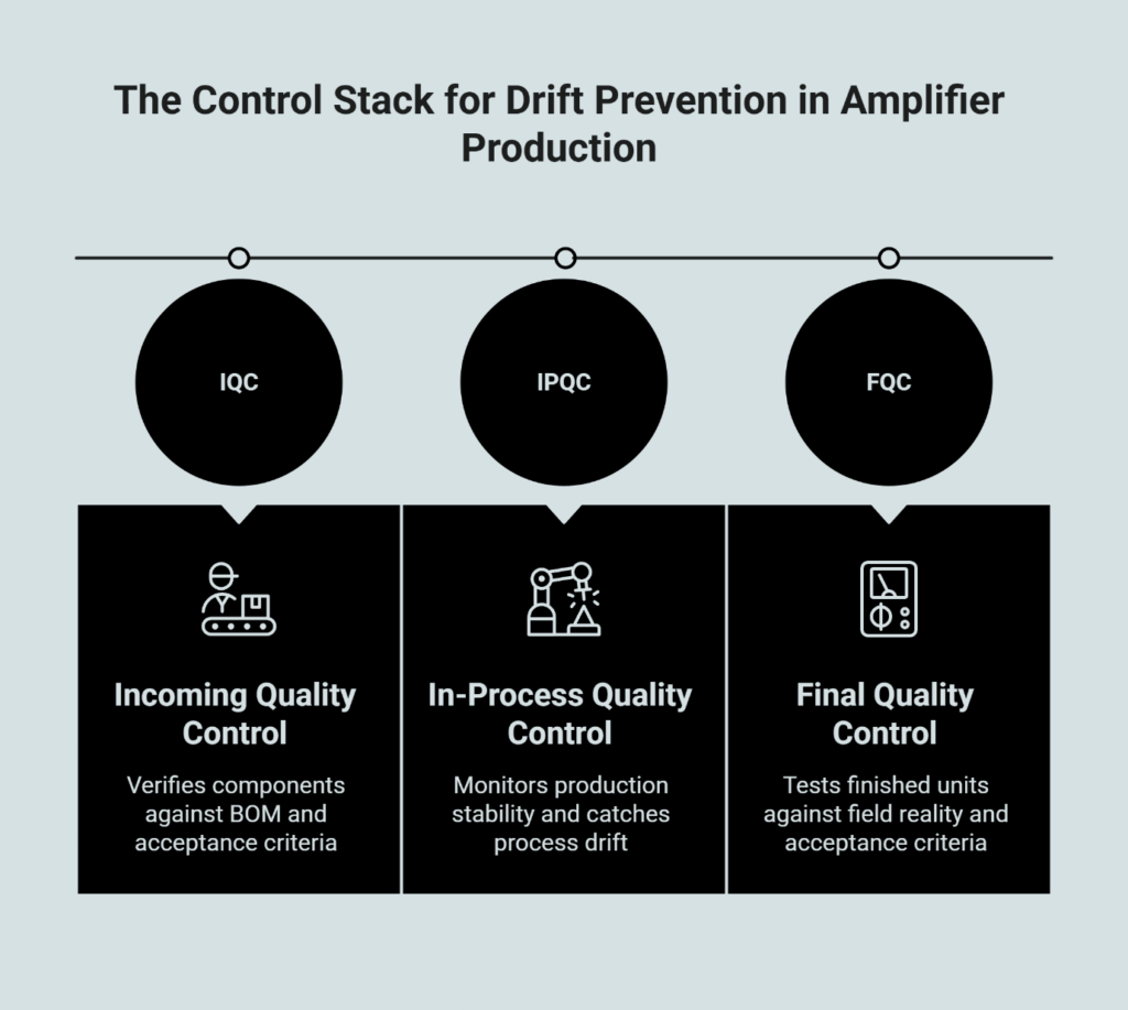
Incoming Quality Control (IQC) is the first mandatory defense against vendor-side drift. IQC prevents substitutions and tolerance shifts from entering the production line in the first place.
Effective IQC requires defining acceptance criteria that match the amplifier’s risk profile. This starts with establishing a critical-to-performance components list—power semiconductors, key passives in feedback and bias networks, thermal interface materials, and protection-relevant sensors all belong on this list. Any deviation from the approved Bill of Materials (BOM) for these specific items mandates a formal deviation request and rigorous acoustic re-validation.
Beyond the critical list, IQC must verify component identity (not just “a capacitor” but this specific part number), lot control documentation, certificates of analysis with actual measured values, and substitution approval workflows. No component should enter the line without explicit authorization if it differs from the approved BOM. Only approved manufacturers and approved alternates should be allowed—anything else triggers a stop-and-review, not a quiet swap. Under ISO 9001:2015 quality management principles, this incoming inspection process forms the foundation of production control.
In-Process Quality Control (IPQC) monitors production stability and catches process drift—the variation introduced by equipment, operators, and environmental conditions. This is where most drift becomes visible, if the gates are designed to catch it.
IPQC includes fixture verification, reflow profile confirmation, limit sample comparisons, and in-line audits. Process parameters need hard limits, not just operator judgment: soldering profile verification, torque specs, thermal interface application controls, and rework limits all require defined thresholds. Station-level test repeatability matters too—calibration schedules, measurement-system checks, and using golden units for test-station validation (not product acceptance) ensure the measurement infrastructure itself isn’t introducing variation.
Early performance signals provide another IPQC layer. Quick, repeatable checks that correlate to later failures—idle current stability, thermal ramp behavior at defined load, noise floor thresholds—can flag drift before it propagates through the entire batch. Statistical process control methods, as documented in the NIST/SEMATECH engineering statistics handbook, provide the analytical framework for detecting when a process has shifted outside control limits.
Final Quality Control (FQC) and end-of-line testing apply objective pass/fail limits to finished units. FQC verifies outcomes with acceptance criteria that match field reality—not merely detecting catastrophic failures, but identifying deviations that matter to users.
This includes functional testing under defined load conditions, thermal behavior verification under stress windows, and acoustic checks against golden sample references. Burn-in and aging protocols must be calibrated to thermal risk profiles. A Class-D amplifier targeting automotive environments requires vastly different sustained-load stress thresholds than a low-voltage consumer smart speaker. FQC is the last gate before shipment and the last opportunity to catch drift before it reaches customers. For a detailed look at how these verification steps work together, see AOI, Functional Test, and Aging: Proof Your Amp Line Is Production Ready.
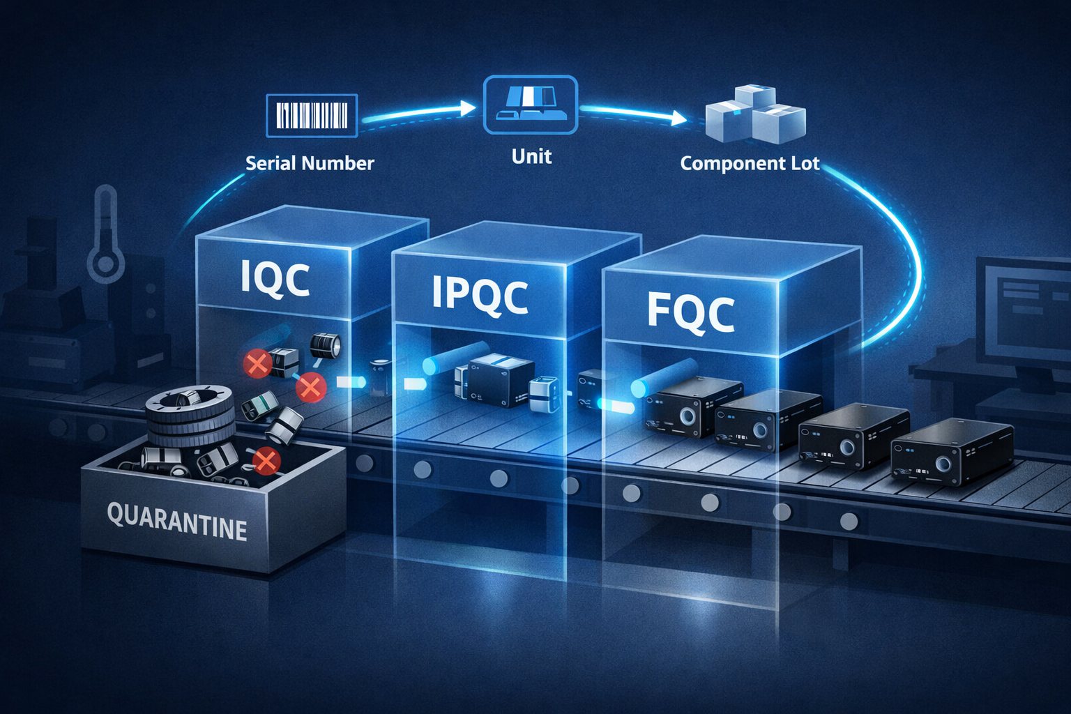
The connection between these gates is traceability. Barcodes and QR codes binding each unit to its component lots, test routes, and measured results enable rapid root-cause analysis when failures emerge. Without traceability, containment is guesswork. With it, containment time drops dramatically because engineering can immediately identify which lots, which shifts, and which fixture stations were involved.
How Component Drift Propagates Through Production
The following illustrates how an unverified tolerance shift cascades from incoming material to field failure—and where quality gates intervene.
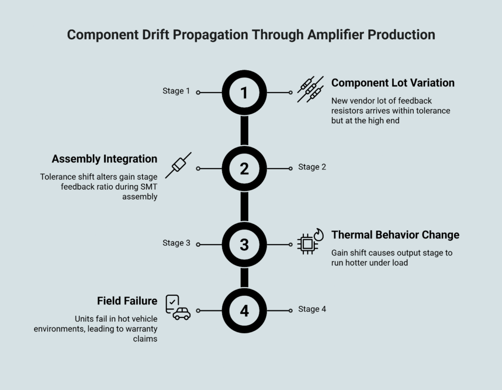
Stage 1: Component Lot Variation A new vendor lot of feedback resistors arrives. Tolerance is within spec (1%), but this lot measures at the high end of the band. → IQC checkpoint: Verify lot documentation, compare to approved vendor list, flag any substitution for engineering review.
Stage 2: Assembly Integration Resistors enter the SMT line. The tolerance shift alters the gain stage’s feedback ratio slightly. → IPQC checkpoint: In-line audits compare output characteristics against limit samples; process control charts flag deviation trends.
Stage 3: Thermal Behavior Change Under sustained load, the gain shift causes the output stage to run hotter. Thermal margin decreases. → FQC checkpoint: Burn-in and aging tests stress units under load; thermal imaging or sensor data flags units exceeding thresholds.
Stage 4: Field Failure Units that passed with marginal thermal margin fail in hot vehicle environments. Field failures mount and warranty costs escalate. → Traceability enables containment: Serial numbers link to component lots; engineering isolates the resistor lot as the root cause; remaining inventory is quarantined.
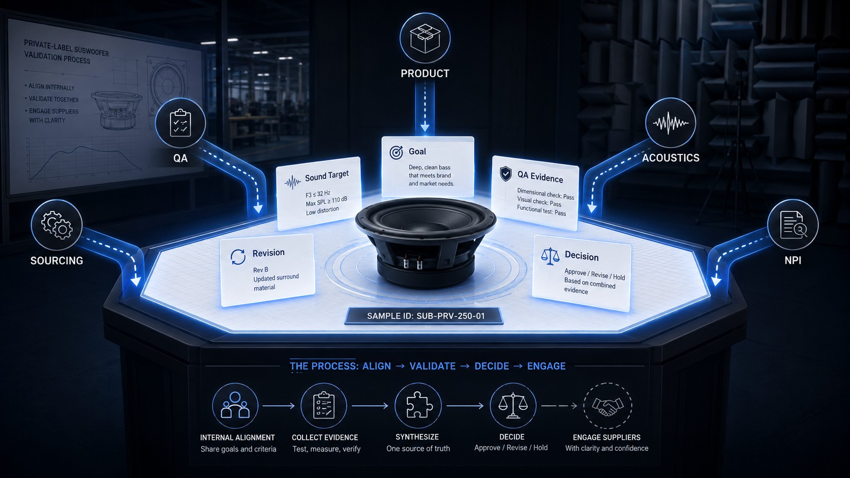
How to Operationalize Drift Prevention with Your OEM Partner
Quality gates are only as strong as the governance agreements that enforce them. Before signing a mass production contract, Sourcing Directors and PM/PMM leads should require three operational commitments.
Define a “no-change” list and ECO cut-in plan. Identify which components are critical to acoustic and thermal performance. These components cannot be substituted without engineering review and explicit approval. For all other components, establish an Engineering Change Order (ECO) workflow that specifies who approves changes, how quickly approval must occur, and how changes are contained to specific serial number ranges. Any change that can affect performance or reliability—component alternates, supplier swaps, process parameter shifts, firmware updates, test method changes—should be treated as controlled change with documented approval and validation.
Require bidirectional traceability. Every finished unit should link to its component lots. Every component lot should link to its vendor COA. Every test result should bind to the unit’s serial number. This traceability chain, aligned with frameworks like NIST’s supply chain traceability guidance, enables containment within hours rather than weeks when failures emerge.
Define escalation thresholds and a containment playbook. What FQC yield rate triggers a line stop? What field failure rate triggers a lot investigation? Who has authority to quarantine inventory? These decisions should be documented before production starts—not improvised during a crisis.
The objective is transforming quality from an inspection activity into a governance system. Inspection catches defects. Governance prevents them.
Frequently Asked Questions
Is a golden sample enough for mass production?
No. While a pre-production unit validates the schematic and initial component synergy, it cannot account for the compounding tolerance stacks and shift-to-shift operator variations inherent to high-volume assembl. Mass production introduces variation from component lots, operators, fixtures, and environmental conditions that the golden sample never experienced.
What is component drift in electronics manufacturing?
Component drift refers to the gradual divergence between approved components and what actually enters production. This includes undocumented vendor substitutions and tolerance-bin variations across lots. Both can remain “within spec” while still altering system-level performance.
How does IQC prevent component substitution?
IQC (Incoming Quality Control) verifies component identity, lot documentation, and certificates of analysis before materials enter the production line. Critically, IQC should include a substitution approval workflow requiring engineering sign-off for any component that differs from the approved BOM.
What traceability do I need to control quality drift?
Effective traceability links finished unit serial numbers to component lot codes, test route records, and measured results. This bidirectional linkage enables rapid root-cause analysis—identifying which lots, shifts, and stations were involved when failures emerge.
What should be in an ECO cut-in plan?
An ECO (Engineering Change Order) cut-in plan should specify which components require engineering approval for substitution, the approval workflow and timeline, how changes are documented, and at which serial number range the change takes effect. This prevents uncontrolled changes from propagating through production.
What should trigger an ECO in an amplifier program?
Any change that can affect performance or reliability warrants ECO treatment: component alternates, supplier swaps, process parameter shifts, firmware updates, and test method changes should all flow through controlled change with approval and validation.
De-Risk Your Next Production Run
Component drift is not a mystery. It is a governed risk—manageable when programs treat quality gates as a system rather than a checklist. The difference between firefighting field failures and shipping with confidence comes down to one question: does your OEM partner have the IQC, IPQC, and FQC discipline to catch drift before it escapes?
For a closer look at how quality systems, testing infrastructure, and traceability work together in amplifier production, explore the production process or read more about why golden sample governance alone isn’t enough.
When you’re ready to discuss acceptance criteria for your next amplifier program, the conversation starts here.
References
[1] ISO 9001:2015 – Quality management systems – Requirements. International Organization for Standardization. https://www.iso.org/standard/62085.html
[2] NIST/SEMATECH e-Handbook of Statistical Methods – Chapter 6: Process or Product Monitoring and Control. National Institute of Standards and Technology. https://www.nist.gov/publications/nistsematech-engineering-statistics-handbook-chapter-6-process-or-product-monitoring
[3] NIST IR 8536 – Supply Chain Traceability: Manufacturing Meta-Framework. National Institute of Standards and Technology. https://csrc.nist.gov/pubs/ir/8536/2pd
Disclaimer: This article provides general information on manufacturing quality management practices for educational purposes. Specific quality requirements vary by product type, regulatory environment, and program scope. Consult with qualified engineering and quality professionals when establishing acceptance criteria for your production programs.